Table of Contents
Introduction:

Technologies for wildlife tracking and ecological monitoring progressed slowly in decades until recent years when GPS receivers can be embedded into tracking collars. In general, modern wildlife tracking and ecological monitoring solutions require three core components: 1) a Global Positioning System (GPS) receiver to track animals’ movements; 2) a wireless communication network to transmit data collected by the GPS; and 3) a battery to prolong the lifespan of the system. For some specialized applications, the system may also incorporate additional sensors to record information of interest about the tracked target, such as the light intensity, humidity, and temperature of its living environment. GPS technologies have matured and can now provide a resolution of several meters.

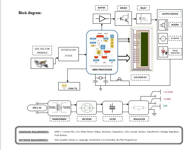
Block diagram explanation:
Power supply unit:
This section needs two voltages viz., +12 V & +5 V, as working voltages. Hence specially designed power supply is constructed to get regulated power supplies.
GPS module:
This is a GPS Receiver (5V Serial) with high gain having 4 Pin 2.54mm pitch strip. The third-generation POT (Patch Antenna on Top) is used by the receiver for the GPS module. It can be interfaced with normal 5V ARM7 with the help of the in-built 3V-5V converter. The interfacing is made easier with the help of a low pin count (4-pin) strip. The 4 Pins are 5V, TX, RX, and GND. This standalone 5V GPS Module does not require external components. It consists of an internal RTC Back up battery and can be directly connected to the USART of the ARM7.
The current date, time, longitude, latitude, altitude, speed, and travel direction / heading among other data, are provided by the module and can be used in many applications including navigation, fleet management, tracking systems, mapping, and robotics. The module can support up to 51 channels. The GPS solution enables small form factor devices which deliver major advancements in GPS performance, accuracy, integration, computing power, and flexibility. They are used to simplify the embedded system integration process.
GSM:
GSM Shield (SIM 900a): The SIM900 which is a complete Quad-band GSM/GPRS solution comes in a SMT module that can be embedded in customer applications. Featuring an industry-standard interface, the SIM900 delivers GSM/GPRS 850/900/1800/1900MHz performance for Data, voice, SMS, and Fax in a small form factor and with low power consumption. SIM900 can fit almost all the space requirements in the M2M application with dimensions of 24mm x 24mm x 3 mm. SIM900 is designed with a very powerful single-chip processor integrating AMR926EJ-S core. Quad-band GSM/GPRS module with a size of 24mmx24mmx3mm, SMT type suit for customer application, An embedded Powerful TCP/IP protocol stack Based upon the mature and field-proven platform, backed up by our support service, from definition to design and production.
NOTE: Modem may change.
ARM processor:
ARM is a computer processor-based RISC architecture. A RISC-based computer design approach means ARM processors require significantly fewer transistors than typical processors in average computers. This approach reduces costs, heat, and power use. The low power consumption of ARM processors has made them very popular:
The ARM architecture (32-bit) is the most widely used in mobile devices, and the most popular 32-bit one in embedded systems.
ARM processor features include:
- Load/store architecture.
- An orthogonal instruction set.
- Mostly single-cycle execution.
- A 16×32-bit register
- Enhanced power-saving design.
Buffers:
Buffers do not affect the logical state of a digital signal (i.e. a logic 1 input results in a logic 1 output whereas logic 0 input results in a logic 0 output). Buffers are normally used to provide extra current drive at the output but can also be used to regularize the logic present at an interface.
Drivers:
This section is used to drive the relay where the output is the complement of input which is applied to the drive but the current will be amplified.
Relays:
It is an electromagnetic device that is used to drive the load connected across the relay and the o/p of the relay can be connected to the controller or load for further processing.
Indicator:
This stage provides a visual indication of which relay is actuated and deactivated, by glowing respective LED or Buzzer.
Methodology:
we are implementing a project called “Wildlife animal tracking using GPS and GSM technology”. In this project, a GPS modem helps to get the coordinates of the location. This modem can require a minimum of 3 satellites Global Positioning System modem receives location parameters like Longitude and Latitude from the satellite. We have also used a GSM modem which sends these parameters to a particular mobile number through SMS. This mobile number can be of a Forest officer or any concerned Government authority person. This SMS will help to track the exact location of the animal. And if an animal moves inside the animal reserves or forest then the particular variable location parameters are received.
Advantages:
- This method is fast and convenient as compared to other systems.
- This does not require human attention as this is a completely self-independent and automated system.
Disadvantages:
- In actual use, this project will be operated on a rechargeable battery. So this battery needs to be recharged. For the longer operation of the battery, we need to use low-power consumption devices, ICs, and components; this will increase the cost of the system.
Applications:
- Wildlife animal tracking — to track the animals in forests and wildlife national parks.
- We can use it for domestic purposes to detect pet animals.
- In criminal cases many times we see that police department uses dogs to find out the traces of criminals, so this project can be used in such situations


