

Table of Contents
Introduction:
Theft of electricity is the criminal practice of stealing electric power. It is a crime punishable by heavy fines and, in some cases, jail.
The most basic method of stealing electricity is a direct wire connection to a main power route passing by a house or shop so that electricity can flow to the consumer without crossing the electric meter installed by a governmental agency that is responsible for providing electrical services to customers. Other methods may include opening the meter itself, without damaging its seals and reversing the dials, a complicated procedure that requires expert skill.
It’s often an “invisible” crime. Someone illegally hooks into a power supply, hooks up a line that has been disconnected, or tampers with a meter to avoid recording electricity usage. Legitimate electricity consumers do not engage in these behaviors, so the impact of electricity theft including the danger is often unrecognized.
Power theft carries deadly risks. Many thieves pay for the power they steal with their lives. Electricity theft is not just dangerous for those who steal. If you are on the same power line as someone who steals electricity, you could pay the cost for their theft too. The power line could become overloaded with electric energy, which could harm your electronics and appliances that are designed to receive a certain, steady amount of electricity. Electricity theft makes power service less reliable and lower quality for paying customers. Electricity thieves may also unknowingly feed energy back into the power line. This is dangerous for linemen who may assume that the power line they are working on is de-energized. Safe Electricity reminds us that everyone can help prevent and reduce power theft:
- Notify your electric utility immediately if you know of an illegally connected consumer.
- Do not cut the seal on your meter base or tamper with your meter for any reason.
- Apply for a legal connection if you do not have one.
- Remain aware of your surroundings and report any suspicious activities to your electric utility.

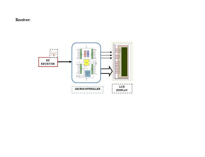
Block diagram explanation
Power supply unit
This section needs two voltages viz., +12 V & +5 V, as working voltages. Hence specially designed power supply is constructed to get regulated power supplies.
IR Transmitter and Receiver:
Infrared (IR) transmitters and receivers are present in many different devices, though they are most commonly found in consumer electronics. The way this technology works is that one component flashes an infrared light in a particular pattern, which another component can pick up and translate into an instruction. These transmitters and receivers are found in remote controls and all different types of devices, such as televisions and DVD players. Peripheral devices that include this technology can also allow a computer to control various other consumer electronics. Since infrared remotes are limited to line-of-sight operation, some products can be used to extend the signals over a hardwired line or radio frequency (RF) transmissions.
Buffers:
Buffers do not affect the logical state of a digital signal (i.e. a logic 1 input results in a logic 1 output whereas logic 0 input results in a logic 0 output). Buffers are normally used to provide extra current drive at the output but can also be used to regularize the logic present at an interface.
Drivers:
This section is used to drive the relay where the output is the complement of input which is applied to the drive but the current will be amplified.
Relays:
It is an electromagnetic device that is used to drive the load connected across the relay and the o/p of the relay can be connected to the controller or load for further processing.
Indicator:
This stage provides a visual indication of which relay is actuated and deactivated, by glowing respective LED or Buzzer.
Methodology:
The proposed project work aims at the design and development of the energy theft prevention aspect. Thereby, energy pilferage can be reduced to a considerable extent. This project envisages the development of energy theft identification. Hence this project work is titled “POWER THEFT MONITORING”. Here electricity board will transmit the energy via RF Transmitter. At the user end the RF Receiver receives the transmitted power from the Electricity Board and provides an acknowledgement about the reception of power by activating a Micro Switch. The acknowledgment information will be transmitted to the head office via RF Transmitter.
Advantages:
- Accurate meter reading and billing.
- Meter readings can be taken even under door-locked cases.
- Useful for detecting faulty and non-reading meters.
- Safe Electricity reminds us that everyone can help prevent and reduce power theft:
- The amount of manpower consumption is decreased considerably, and the recording of energy meter readings and preparation of bills are simplified [if data is stored in an external memory device].
- Motivation for conversation.
- For detecting tampering and theft of power.
Disadvantages:
- One-time cost investment.
Applications:
- Real-time Power monitoring at houses.
- Sensing the power theft at the exact location.
- Transmitting the information over wireless, to substation.
- It can be used in domestic households.
- It can be implemented in malls where huge amounts of power are wasted.
- It can also be implemented in schools and colleges.
- The system can be incorporated for almost all types of users.
- The concept is well suited, especially for villages and interior areas