

Table of Contents
Introduction:

Automation for transmission lines is the current trend, which transforms the mere conveyer into a well-furnished moving home-like feeling. As the country is opened to globalization, people’s income is rising. And traveling now becomes an essential part of life. So, governments prefer not only to raise their road quality but also the width of it. As a result, transmission lines are flowing throughout the country like blood veins. This leads to more transmission lines Throughout the country.
This increase in the number of transmission lines brings not only revenue but also a headache to the substation office, Department, and others too. It is hard to keep & maintain the details of each transmission line; this inefficiency sets some evil things to work on. Such as, in case of faults or carrying other faults over inter-state cross border or road cases, people of substation may not trace the faults very easily, as the transmission line details are not monitored continuously.
So to overcome such problems, Global Positioning System [GPS] was introduced. In this system, transmission lines are tracked using Low Earth Orbit Satellites continuously. Not only this, the transmission line owner can see the road map of the location on which he is heading or weather report/forecast of his locality or whether the heading road is clear or traffic-jammed and if the road is blocked which is the alternative way to reach the destination, etc.
The Project is not about the GPS, but about alternative technology which is much more economical, simple, and Indigenous in design. Thereby resulting in an effective system for our network system of transmission line monitoring facility from a remote end like the control room.
With the help of this project, it is possible to easily track particular transmission lines for their geographical locations on an LCD screen. The operator can see the transmission line’s current location in real-time mode. Here the communication network is comparable to the cellular network in operation. So whenever a transmission line equipped with its ID Transmitter enters a “cell” / geographical location, that particular “Cell Unit” or “Cell Broadcaster” sends a wireless message to the centralized base unit. In turn, the base unit receives the VHF message from the “Cell Broadcaster” and after processing & decoding displays the geographical location of the transmission line in a graphical form on the computer monitor screen. This way the user can find the whereabouts of the transmission line in real-time mode & if for any reason needs it necessary to lock/immobilize the transmission line under observation; he can do so with the help of control software installed in the PC.
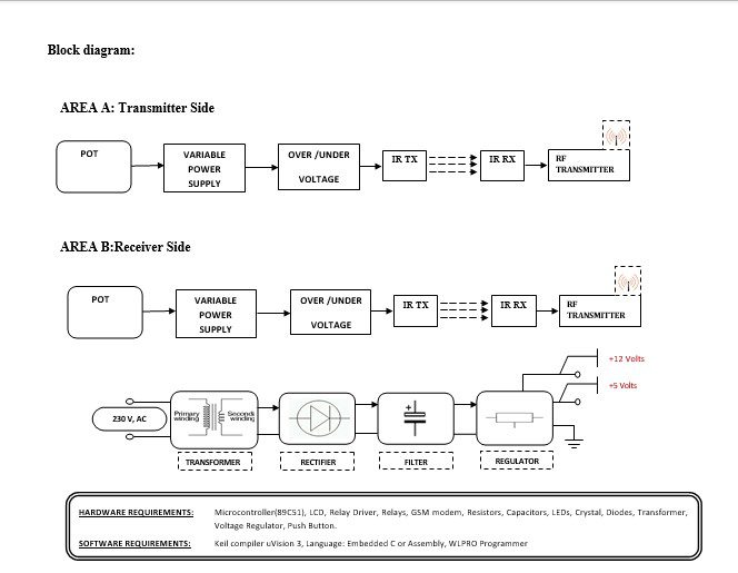
Block diagram explanation :
Power supply unit:
This section needs two voltages viz., +12 V & +5 V, as working voltages. Hence specially designed power supply is constructed to get regulated power supplies.
RF transmitter:
This is a 2-channel Radio Frequency Transmitter specially tuned with its RF Receiver part in carrier frequency. Each zone is set with one channel and transmits its presence to the moving vehicle’s RF Receiver unit.
RF receiver:
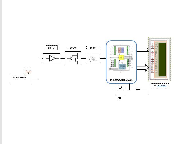
This is also a 2-channel RF Receiver specially tuned with its counterpart RF Transmitter in carrier frequency. When a vehicle enters any zone that zones RF signals are received by this unit. Thus depending upon the channel signals it receives from the transmitting end the channel output of the RF Receiver goes HIGH. This HIGH signal is fed to the controller chip through Buffer & Driver and Switching stage for further processing.
Buffers:
Buffers do not affect the logical state of a digital signal (i.e. a logic 1 input results in a logic 1 output whereas logic 0 input results in a logic 0 output). Buffers are normally used to provide extra current drive at the output but can also be used to regularize the logic present at an interface.
Drivers:
This section is used to drive the relay where the output is the complement of input which is applied to the drive but the current will be amplified.
Relay:
It is an electromagnetic device that is used to drive the load connected across the relay and the o/p of the relay can be connected to the controller or load for further processing.
Indicator:
This stage provides a visual indication of which relay is actuated and deactivated, by glowing respective LED or Buzzer.
IR Transmitter & Receiver :
Infrared (IR) transmitters and receivers are present in many different devices, though they are most commonly found in consumer electronics. The way this technology works is that one component flashes an infrared light in a particular pattern, which another component can pick up and translate into an instruction. These transmitters and receivers are found in remote controls and all different types of devices, such as televisions and DVD players. Peripheral devices that include this technology can also allow a computer to control various other consumer electronics. Since infrared remotes are limited to line-of-sight operation, some products can be used to extend the signals over a hardwired line or radio frequency (RF) transmissions.
Microcontroller:
The 89C51 Microcontroller is the heart of this project. It is the chip that processes the User Data and executes the same. The software inherited in this chip manipulates the data and sends the result for visual display.
The general definition of a microcontroller is a single-chip computer, which refers to the fact that they contain all of the functional sections (cpu, ram, rom, i/o, ports, and timers) of a traditionally defined computer on a single integrated circuit. Some experts even describe them as special-purpose computers with several qualifying distinctions that separate them from other computers.
Features Of Microcontroller :
- 8K Bytes of In-System Reprogrammable Flash Memory
- Endurance: 1,000 Write/Erase Cycles
- Fully Static Operation: 0 Hz to 24 MHz
- Three-level Program Memory Lock
- 256 x 8-bit Internal RAM
- 32 Programmable I/O Lines
- Three 16-bit Timers/Counters.
PHS technology:
| Innovative mobile system to deliver high-quality voice and data transmission capabilities at low cost. Kyocera PHS System — making communications better around the world. The PHS service was launched first in 1995 to respond to the diversified demand for mobile communication in Japan. In January 2000, PHS network services with Kyocera cell stations were started in China. Since then, subscribers have been steadily increasing in China and Impressive development centering on Southeast Asia is also seen to be growing. Kyocera has been the major supplier of PHS equipment in Japan as well as in China and Southeast Asian markets. |
Methodology:
The above block diagram shows the setup of the fault finder using PHS. The job of this RF / IR transmitter is to transmit continuously if any fault like over or under voltage in the transmission line on which it is mounted, in coded form. When any fault finds in zone A, the sensors sense “an over/under voltage “. This signal is transmitted
Through RF Tx to the receiver side. The receiver side receives the signal by RF Rx Then is displayed on the LCD through the microcontroller.
Advantages:
- Effective in implementation.
- Low power consumption, and compact size,
- High reliability, due to the usage of power semiconductor devices,
- Greater control range due to the usage of Frequency Modulation with a PC.
- Transmission lines are monitored from a remote area (no need for a ‘line-of-sight’ arrangement).
Disadvantages:
One-time investment.
Applications:
- High-quality voice transmissions
- In contrast to cellular systems, PHS Systems do not require an independent network. This means that preexisting network facilities can continue to be fully utilized
- Exceptional mobility even with microcells.
- In Vehicles, Mobiles.