Table of Contents
Introduction:

Nowadays, home automation using wireless communication is replacing the wired system which was difficult to set up. Wireless sensor networks (WSNs) have been utilized all over the world. The wireless sensor networks can be used in many consumer and industrial applications, such as machine health monitoring and control, environment and habitat monitoring, biomedical health monitoring, home automation, traffic control, natural disaster relief, and seismic sensing. Wireless sensor networks in the home are easy to establish without using cables and offer greater coverage. Several studies say that Wireless sensor networks are a cost-effective solution for collecting, receiving, and transmitting data. Home/office automation consists of security, heating, ventilation, air-conditioning (HVAC), lighting control, access control, and electrical appliance control.
Under a smart home environment, numerous sensors i.e. detectors for temperature, smoke, gas leakage, fire, PIR and light, etc., and communication devices can be utilized for connection throughout the house, capable of monitoring and detecting the events. The input from these sensors can be used to alert the owner of any intrusion done in an unauthorized way or control home appliances such as lighting, air conditioner. Thus, maintaining seamless connectivity between devices and the main controller is very crucial A lost connectivity can jeopardize the security of the home. There are many related works concerning the design of home/office automation control using wireless sensor networks.

Block diagram explanation :
Power supply unit:
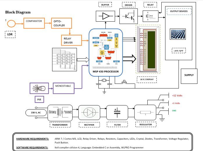
This section needs 2 voltages +12 and +5 volts, as a working voltage Hence specially designed power supply is constructed to get a regulated power supply.
Comparator:
Here comparator is used to compare the i/p from LDR and compares the light intensity and generates the output accordingly. The o/p of this comparator is then applied to MSP 430 via the Relay driver unit.
MSP 430 Controllers:
Here the MSP 430 is used to check the password which has been entered from the keyboard. If the password is correct it generates the output accordingly. The output of this section is connected to Buffer & Driver unit for further processing.
Buffer:
Buffers do not affect the logical state of a digital signal (i.e. a logic 1 input results in a logic 1 output whereas logic 0 input results in a logic 0 output). Buffers are normally used to provide extra current drive at the output but can also be used to regularize the logic present at an interface.
Driver:
This section is used to drive the relay where the output is the complement of input which is applied to the drive but the current will be amplified.
Relay:
It is an electromagnetic device that is used to drive the load connected across the relay and the o/p of the relay can be connected to the controller or load for further processing.
Sensor:
1. Passive Infrared Sensor
A Passive Infrared sensor (PIR sensor) is an electronic device that measures infrared (IR) light radiating from objects in its field of view. PIR sensors are often used in the construction of PIR-based motion detectors. Apparent motion is detected when an infrared source with one temperature, such as a human, passes in front of an infrared source with another temperature, such as a wall. This is not to say that the sensor detects the heat from the object passing in front of it but that the object breaks the field which the sensor has determined as the “normal” state. Any object, even one the same temperature as the surrounding objects will cause the PIR to activate if it moves in the field of the sensors.
2. Light Dependent Resistor
Light-dependent resistor (LDR) is a resistor whose resistance decreases with increasing incident light intensity; in other words, it exhibits photoconductivity. It can also be referred to as a photoconductor or CdS device, from “cadmium sulfide,” which is the material from which the device is made and that exhibits the variation in resistance with light level. A photoresistor is made of a high-resistance semiconductor. If light falling on the device is of high enough frequency, photons absorbed by the semiconductor give bound electrons enough energy to jump into the conduction band. The resulting free electron (and its hole partner) conduct electricity, thereby lowering resistance.
Methodology:
When a person enters the in-home/office password has to be entered and the password is verified by the controller if the entered password is correct then the door will be opened and depending on the sensors automation can be controlled. The lighting model uses Light Emitting Diodes (LEDs) which are driven by a driver. The output of LDR is connected to comp this lighting model is controlled by Comparator which receives the commands from the LDR or a manually controlled system. To this lighting model, different sensors are also connected as shown in the diagram.
Applications:
1. Password-Based Locking System.
2. Fire and Smoke sensor
3. Light-saving system
4. Temperature-controlled cooling system
5. Counter-dependent automatic switching system of room
Advantages & Disadvantages:
Advantages:
1. Walking up to the regulator’s board to change the fan speed is avoided.
2. Unnecessary wastage of electricity can be controlled to a greater extent.
3. Maximum power can be saved.
4. Selectable Sensitivity, Sensitivity can be adjusted to match installation requirements.
5. Wide supply voltage range: 3.0V to 15V in COMPARATOR.
Disadvantages:
- The high capital expenditure required to invest in automation (an automated system can cost millions of dollars to design, fabricate, and install).
- A higher level of maintenance is needed than with a manually operated machine, and a generally lower degree of flexibility in terms of the possible products as compared with a manual system.
- Also, there are potential risks that automation technology will ultimately subjugate rather than serve humankind.


