Table of Contents
Introduction:

Providing safety to a person while riding the bike is of prime concern. One of the ways to do this is by making it mandatory to wear a helmet while riding a bike. This is difficult to implement as every time the concerned people can’t keep an eye on everybody. So detecting whether the driver has worn a helmet or not, as well as whether he has consumed alcohol or not is the main problem. The system that we have planned to design provides a solution to this problem. The system makes it mandatory for the rider to wear a helmet before starting the vehicle and also he shouldn’t have consumed alcohol. If the rider fails to do so then the vehicle cannot be started. This system also provides security to the vehicle as every bike will have a unique helmet and without which a person fails to start that particular bike. This project includes a helmet body and an integrated electronic system disposed of in the helmet body. It is operated through a wireless control system. The components of the electronic system are sufficiently small and rugged for use in the helmet, ensuring that the helmet is lightweight and durable. Moreover, the components are spaced about the helmet to provide even weight distribution to promote overall balance and safety.


Block diagram explanation :
Power supply unit:
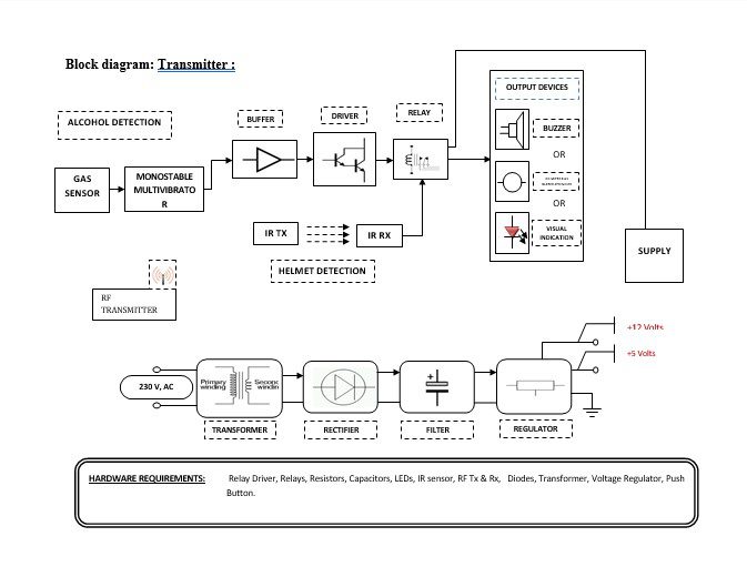
This section needs two voltages viz., +12 V & +5 V, as working voltages. Hence specially designed power supply is constructed to get regulated power supplies.
Buffers:
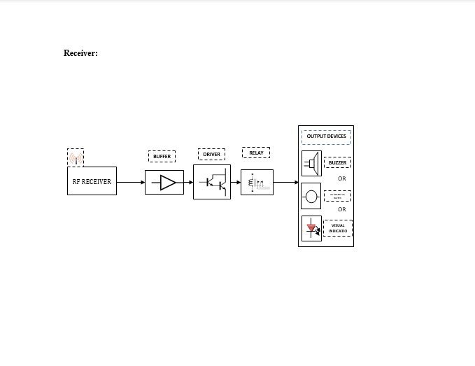
Buffers do not affect the logical state of a digital signal (i.e. a logic 1 input results in a logic 1 output whereas logic 0 input results in a logic 0 output). Buffers are normally used to provide extra current drive at the output but can also be used to regularize the logic present at an interface.
IR Transmitter and Receiver:
Infrared (IR) transmitters and receivers are present in many different devices, though they are most commonly found in consumer electronics. The way this technology works is that one component flashes an infrared light in a particular pattern, which another component can pick up and translate into an instruction. These transmitters and receivers are found in remote controls and all different types of devices, such as televisions and DVD players. Peripheral devices that include this technology can also allow a computer to control various other consumer electronics. Since infrared remotes are limited to line-of-sight operation, some products can be used to extend the signals over a hardwired line or radio frequency (RF) transmissions.
Drivers:
This section is used to drive the relay where the output is the complement of input which is applied to the drive but the current will be amplified.
Relays:
It is an electromagnetic device that is used to drive the load connected across the relay and the o/p of the relay can be connected to the controller or load for further processing.
Indicator:
This stage provides a visual indication of which relay is actuated and deactivated, by glowing respective LED or Buzzer.
RF transmitter:
This is a 2-channel Radio Frequency Transmitter specially tuned with its RF Receiver part in carrier frequency. Each zone is set with one channel and transmits its presence to the moving vehicle’s RF Receiver unit.
RF receiver:
This is also a 2-channel RF Receiver specially tuned with its counterpart RF Transmitter in carrier frequency. When the vehicle enters any zone that zones RF signals are received by this unit. Thus depending upon the channel signals it receives from the transmitting end the channel output of the RF Receiver goes HIGH. This HIGH signal is fed to the controller chip through Buffer & Driver and Switching stage for further processing.
Methodology:
The block diagram consists of two parts. One part is to be implemented in the helmet and consists of a transmitter and the other in the bike which consists of a receiver. The transmitter part interprets the required condition and the microcontroller generates the code sequence continuously which is ported to the transmitting block. This transmitting block can be an IR module. This signal is transmitted to the receiver. The receiver decodes this signal based on which it takes necessary action like turning on/off the ignition system. The first step is to detect whether the driver is wearing a helmet or not. For this purpose, we can use IR sensors. The second condition is to check whether the rider is drunk or not. To check this we are using an alcoholic detector interfaced with the control circuit, which is placed near his mouth in the helmet. The wireless network can be implemented by the RF (radio frequency) transmission/reception. With the help of RF we can intimate the rider is drunk or not wearing a helmet to the police station or concerned person.
Advantages:
- No Manual attention is needed.
- Reduces driver’s job by automatically responding to approaching vehicles.
- The circuit is flexible, without much change in the circuit; it can be used with any 4-wheeler.
Disadvantages:
- Damage to the sensor cannot be detected.
- One-time investment cost.
Applications:
- This project can be used for all kinds of two-wheeler.
- Further, this project can be to eliminate key-lock arrangement.
- This project can also be implemented in a confined area / geological area, to restrict the movement of vehicles including two-wheelers.
- This project is very useful for confidential meetings, secret occasions, and other similar requirements.
- Near the petrol Pumps, LPG Storages & Explosive Storage Places to prevent any possible damage due to the Cell Phone / GSM frequency, which may trigger an explosion.
- In the military Camps, Defense establishments, etc to prevent information leaking.
- The cell phone may cause malfunctioning of the Bio-Medical Equipment. So this project can be used in hospitals to detect the active mobile device.


