Table of Contents
Introduction:

The smart home is a home equipped with special facilities to enable occupants to control or program an array of automated home electronic devices. For example, a homeowner on vacation can arm a home security system, control temperature gauges, switch appliances on or off, control lighting, program a home theater or entertainment system, and perform many other tasks. Smart homes became smarter if the controlling can be done from any remote place. Our main focus is to control home appliances from remote places.

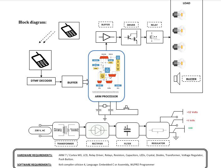
Block diagram explanation:
Power supply unit:
This section needs 2 voltages +12 and +5 Volts, as working voltages Hence specially designed power supply is constructed to get a regulated power supply.
Arm 7:
The heart of the system is the microcontroller which will access the data. In our project, ARM7 is used. The ARM7 which we used for our project is LPC2148 (PHILLIPS) ARM7 is a high-performance, low-cost, low-power consumption RISC processor. For a variety of areas, such as embedded control, multimedia, DSP, and mobile applications, ARM architecture is the first RISC microprocessor designed for the low-budget market. The embedded operating system will be subject to certain restrictions. But because of its low price, reliability, and other factors, it is widely used in various industrial controllers.
Buffer:
Buffers do not affect the logical state of a digital signal (i.e. a logic 1 input results in a logic 1 output whereas logic 0 input results in a logic 0 output). Buffers are normally used to provide extra current drive at the output but can also be used to regularize the logic present at an interface.
Driver:
This section is used to drive the relay where the output is the complement of input which is applied to the drive but the current will be amplified.
Relay:
It is an electromagnetic device that is used to drive the load connected across the relay and the o/p of the relay can be connected to the controller or load for further processing.
Decoder:
On the receiver side, the received signals of different frequencies are passed to the DTMF decoder IC through mobile which will convert it into a BCD signal. These BCD signals are used to control the equipment.
Methodology:
In this paper, a remote control system is developed to perform controlling actions using a mobile phone. The proposed system can receive DTMF signals and sends them via decoder to an ARM controller and then to a driving system that in turn will control the target device. The DTMF signal is generated when the keypad button is pushed by the user – mobile phone, then this signal is decoded to Binary Decimal Digits (BCD) by the DTMF decoder, after that the BCD is sent to the ARM controller.
The following steps describe how the proposed system operates:
1. The user sends the DTMF tone to the decoder through the mobile.
2. DTMF decoder will send to the ARM controller the appropriate signal (coded DTMF tone in the form of BCD suitable for the ARM controller.
3. An interrupt is done and the signal will be loaded to the memory of the ARM controller.
4. The ARM controller processes the obtained signals from the decoder and the LEDs will glow at the specified output pins of the ARM controller indicating the processed signals.
5. These processed signals will send to the driving system that contained the relays, which must regulate the motion of the motor in the required direction.
6. Programming an ARM controller ship in such a way for responding to user requirements on how to control the target device.
APPLICATIONS
1) Combination Lock
2) Home Security System
3) Mobile / Wireless Robot control
4) Wireless Radio Control
5) Continuous monitoring of system status
6) Remote Switches
7) Reporting during car accidents
Advantages & Disadvantages
Advantages
1. Less human effort
2. User friendly
3. Time Effective
4. Security
Disadvantages
- One-time investment is costly.


