Table of Contents
Introduction:

Optical communications have been used in various forms for thousands of years. After the invention of light amplification by stimulated emission of radiation (LASER) sources and light-emitting diodes (LED’) in the 1960s, optical communication quickly revolutionized and spread around the world. Wireless networking is dominated by the use of radio frequency (RF) techniques. The desire for low-cost, high-speed links motivated recent interest in infrared (IR) wireless communication. The theoretical background for visible light communication (VLC) systems is similar to that found in IR communication except that VLCs use a much wider visible spectrum. A recent report shows that usage of mobile web and Wi-Fi by smartphones is increasing sharply. Accommodating this growing wireless demand with cellular capacity does not seem possible in the long run. At the same time, the rapid development of new LED materials in the visible spectrum, especially white LED motivates considerations of visible light communication medium since it is expected to be widely used as the next form of illumination. Full use of the capacity provided by fiber delivered to homes will necessitate the use of broadband links including indoor wireless access technologies capable of operating at Gbit/s. In recent years optical wireless (OW) has emerged as a strong candidate for high-speed indoor communication.
Indoor optical wireless communication includes two main technologies: visible light and infrared communications. Concerns about energy saving in general lighting are leading to the replacement of incandescent and fluorescent lamps with more energy-efficient solid-state lighting (SSL) devices. These SSL visible light sources can provide communications as well as illumination. And this emerging technology has recently drawn great interest in research and practical applications. The LED-based visible light optical channel becomes a very attractive complement or even substitute for RF techniques. It has the advantage of large potential bandwidth (THz) with no regulation or license fee. Finally in addition to lower energy consumption LEDs have a significantly longer lifetime and are safer for the environment lifetime as they lack the harmful ingredient of mercury.


Block-Diagram Explanation
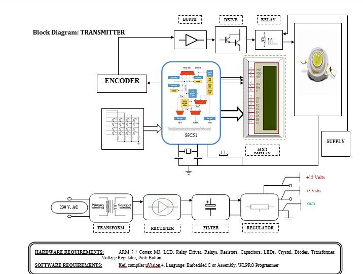
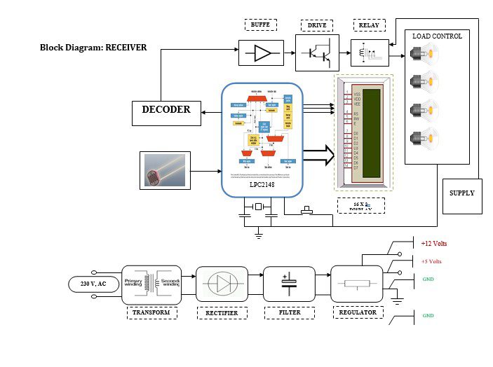
A VLC system used to transmit high-quality video and audio signals was proposed and demonstrated by using illumination LEDs. The analog signals were transmitted using the illumination LEDs in the transmitter. The photodiode at the receiver senses optical signals from the LEDs and is converted into electrical signals. The electrical signal is then amplified to recover the digital signal and converted back to analog signals. To obtain this signal is amplified to increase the strength such that it will drive the preceding stage such as power LED and its driver and to remove noise capacitor filter is used.
This project can make use of Light as a source of medium to transmit the signals as it is known that light is ambient and it doesn’t affect human life or nature here we are transmitting the audio signals via light.
Power supply unit:
This section needs 2 voltages +12 and +5 Volts, as working voltages Hence specially designed power supply is constructed to get a regulated power supply.
Arm 7:
The heart of the system is the microcontroller which will access the data. In our project, ARM7 is used. The ARM7 which we used for our project is LPC2148 (PHILLIPS) ARM7 is a high-performance, low-cost, low-power consumption RISC processor. For a variety of areas, such as embedded control, multimedia, DSP, and mobile applications, ARM architecture is the first RISC microprocessor designed for the low-budget market. The embedded operating system will be subject to certain restrictions. But because of its low price, reliability, and other factors, it is widely used in various industrial controllers.
Buffer:
Buffers do not affect the logical state of a digital signal (i.e. a logic 1 input results in a logic 1 output whereas logic 0 input results in a logic 0 output). Buffers are normally used to provide extra current drive at the output but can also be used to regularize the logic present at an interface.
Driver:
This section is used to drive the relay where the output is the complement of input which is applied to the drive but the current will be amplified.
Relay:
It is an electromagnetic device that is used to drive the load connected across the relay and the o/p of the relay can be connected to the controller or load for further processing.
Switching unit:
In device control application input is given from the keypad. When the button is pressed on the keypad a connection is made that generates two tones at the same time. A “Row” tone and a “Column” tone. These two tones identify the key pressed for any device to be controlled. When the user presses any particular switch then the DTMF encoder IC will generate a unique pair of frequencies. And accordingly, the different keys are pressed signals of different frequencies are generated. This code sequence will be fed to an LED which will emit the light according to the sequence generated i.e. it will turn on for logic 1 and turn off for logic 0. Then this light signal is transmitted to the receiver side where it is reproduced as an electrical signal through a light dependant resistor. On the receiver side, the received signals of different frequencies are passed to the DTMF decoder IC which will convert it into a BCD signal. These BCD signals are used to control the equipment.
Methodology
- OFDM
OFDM is a popular multi-carrier modulation technique developed for RF systems able to significantly increase the data rate in bandwidth-constrained channels. Because of its outstanding performance in RF systems, modified forms of it, such as DC-biased optical OFDM (DCO-OFDM) and asymmetrically clipped optical OFDM (ACO-OCDMA), have been proposed for use in indoor VLC systems. Bit rates of 1 Gb/s in combination
Several challenges remain in using OFDM for VLC. The tails of the impulse response can be quite long, requiring a long cyclic prefix for OFDM to work, and this reduces the throughput. Dimming is another challenge in utilizing OFDM in indoor VLC. OFDM has a naturally high PAPR, but it is not easily controllable. A solution for embedding the dimming function in OFDM is to combine it with PWM, as suggested, but this approach limits the data rate and can cause a flicker. By far the worst problem for OFDM is the LED nonlinearity since, due to the large PAPR; it can severely distort the output signal.
2. SPATIAL MODULATION
To side-step the single-degree-of-freedom limitation of IM, a multi-point system can be used. The resulting so-called spatial modulation (SM) increases the data transmission rate by using multiple physically-separated transmitters and multiple physically-separated receivers. SM can either be used as a stand-alone modulation or be considered as a form of multiple-input multiple-output (MIMO) that can be combined with other modulation schemes to increase the bit rate.
The main drawback of SM in the VLC system is its susceptibility to shadowing and multipath interference.
Applications
- Aviation
- Smart Lighting
- Hazardous Environments
- Device Connectivity
- Vehicle and Transportation
- Defense and Security
- Hospitals
- Underwater Communications
Advantages & Disadvantages
Advantages
1. Harmless for the human body.
2. Data transmission by sockets of existing light fixtures.
3. Alleviation of problems associated with the radio frequency (RF) communication system.
4. Less energy consumption.
5. Increased security.
6. Compact integration of sensors through small dimensions.
7. Huge number of channels available without interfering with other sources.
8. Simple electronics such as the drive for the LEDs.
9. No influence on other sensitive equipment through radio waves.
Disadvantages
1. To transmit the data it should be in the line of sight.


