Table of Contents
Introduction:

Fuel costs are rising and emissions restrictions are getting tighter all over the world. Automakers are required to comply, but at the same time do not want to sacrifice performance or raise prices to put themselves at a competitive disadvantage. Technologies such as variable valve timing, cylinder deactivation, and direct injection can help automakers simultaneously boost power and fuel efficiency. Each technology is analyzed for its fuel and cost requirements and its feasibility for implementation.
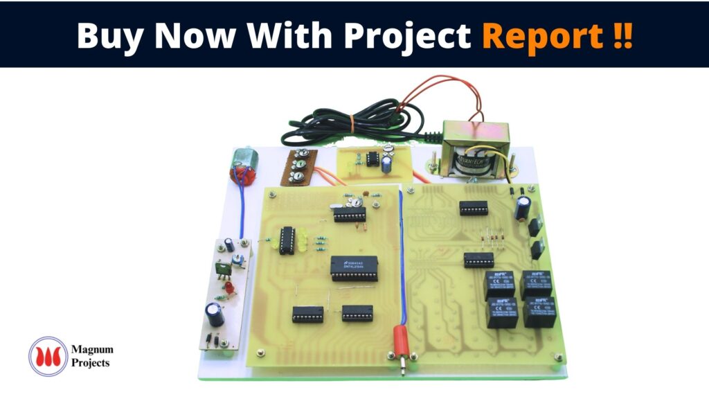
Here is a novel effort to demonstrate the functioning of such technologies concerned with modern automobile industry requirements. The Engine Management System project presented here is an advanced system for the petrol engine vehicles like bikes & even Cars. Here the project is designed to monitor various parameters related to the petrol vehicle and accordingly control the parameters like Ignition, Fuel quantity, choking, etc. Here the project is controlled by electronic circuits which keep on monitoring the engine and making decisions.

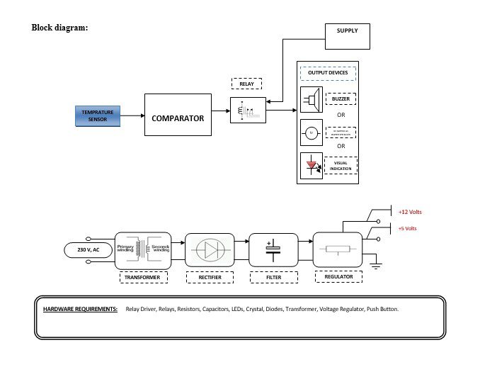
Block diagram explanation :
Power supply unit:
This section needs two voltages viz., +12 V & +5 V, as working voltages. Hence specially designed power supply is constructed to get regulated power supplies.
Buffers:
Buffers do not affect the logical state of a digital signal (i.e. a logic 1 input results in a logic 1 output whereas logic 0 input results in a logic 0 output). Buffers are normally used to provide extra current drive at the output but can also be used to regularize the logic present at an interface.
Drivers:
This section is used to drive the relay where the output is a complement of input that is applied to the drive but the current will be amplified.
Relays:
It is an electromagnetic device that is used to drive the load connected across the relay and the o/p of the relay can be connected to the controller or load for further processing.
Indicator:
This stage provides a visual indication of which relay is actuated and deactivated, by a glowing respective LCD or Buzzer.
Comparator:
This part reads the user card, if found valid then it processes next. This card automatically recognizes the privilege level. The heart of this card reader is the popular Operational Amplifier IC. Here every card offers some unique amount of resistance to the card reader block. Depending upon the resistance the card offers, the card reader comes to know what privilege the cardholder got.
Methodology:
The above block diagram shows the setup Safety Engine management system Using a Temperature sensor. This project consists of a set of sensors to read the Engine Temperature. According to the gathered information through a set of sensors, and the setting of the Electronic Logic Stage, the output electrical devices are operated to control the following parameters related to the Petrol Engine viz., Any variation in temperature sensor occurs that output signal is fed comparator it compares in the comparator. The comparator compared temperature according to that generates the output put that is fed to buffer IC 4050, buffer stores and given to the driver IC 2003 in driver current will amplify and voltage will invert with the help of Darlington pair circuit of driver IC to drive the relay. Then the signal is given to the output load.
Advantages:
- Improved Fuel Efficiency.
- Better Engine Performance.
- Low Pollution.
- Efficient & Intelligent Engine Operation.
- Low Fuel Consumption.
Disadvantages:
Sensor failure causes problems.
Applications:
- Automotive Applications.
- Smart environment.
- Environmental Applications.
- Military Applications.
- Monitoring friendly forces, equipment, and ammunition.
- Battlefield surveillance.


