Table of Contents
Introduction:


In this sophisticated world, every activity is getting atomized with the help of embedded concepts. All the way so far we have seen that any controlling of parameters, utilizing natural resources for circuit operation, preventing the devices from electric disorders, optimizing, etc…, is carried out with analog instruments. So we decided to develop an electronic aid which is helpful for the above purpose which is called as. Embedded Design Using MSP 430 For Strong Room Security System
In automation and instrument building we often are confronted by the necessity to precisely control the illumination of light, the rotational speed of a fan, controlling the devices depending on the detection of human being present in the room or not, and device switching using remote. Their illumination can be controlled by switching ON the number of LED as per requirement; depending on the room temperature speed of the FAN or conditioning unit of AC can be controlled as a function of applied voltage. Here is a project for. Embedded Design Using MSP 430 For Strong Room Security System
It monitors the surrounding environment and electrical conditions depending on those parameters the embedded system will control the operation of the devices. like, if the room temperature is increased more than the desired temperature the system will automatically control the speed of the fan, in other condition it will check for the natural light intensity depending on that microcontroller will control how many sets of LEDs should be switched ON, similarly one of the main features of this project is PIR sensor, this sensor is used to detect the presence of anybody in the room or not concerning that the system will control the action of devices such that switching ON/OFF and this project works on the dc power supply, in presence of sunlight the circuit will work with power generated by the solar cells else with the main power supply.


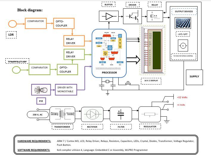
Block diagram explanation :
Power supply unit:
This section needs two voltages viz., +12 V & +5 V, as working voltages. Hence specially designed power supply is constructed to get regulated power supplies.
Comparator:
This part reads the user card, if found valid then it processes next. This card automatically recognizes the privilege level. The heart of this card reader is the popular Operational Amplifier IC. Here every card offers some unique amount of resistance to the card reader block. Depending upon the resistance the card offers, the card reader comes to know what privilege the cardholder got.
MSP 430 Controllers:
The MSP430 is a mixed-signal microcontroller family from Texas Instruments. Built around a 16-bit CPU, the MSP430 is designed for low-cost and, specifically, low-power consumption embedded applications.
Buffers:
Buffers do not affect the logical state of a digital signal (i.e. a logic 1 input results in a logic 1 output whereas logic 0 input results in a logic 0 output). Buffers are normally used to provide extra current drive at the output but can also be used to regularize the logic present at an interface.
Drivers:
This section is used to drive the relay where the output is the complement of input which is applied to the drive but the current will be amplified.
Relays:
It is an electromagnetic device that is used to drive the load connected across the relay and the o/p of the relay can be connected to the controller or load for further processing.
Indicator:
This stage provides a visual indication of which relay is actuated and deactivated, by glowing respective LED or Buzzer.
Methodology:
PIR Sensor:
The space to be monitored is divided by the lens into several zones. The number of zones depends on the number of segments of which the lens is composed. When somebody moves from one zone to another, there is a temperature change which is collected by the lens as a variation in radiant energy. As the focus of the lens is a hydroelectric sensor that reacts to such a change by generating a small electric signal. That signal is processed and used to actuate/deactivate the appliances.
LDR Sensor:
Depending on the natural light intensity number of LEDs should be switched ON and OFF. This operation should be performed using COMPARATOR and ARM. Whenever the light intensity in a room varies depending on that a digital signal has to be generated using COMPARATOR which should be given to the MSP430. In the controller, a decision has to be made that how many LEDs should turn ON or OFF. In the above Fig 2, the LED array is shown in 4 numbers because a single LED array consists of 9 LEDs therefore total of 3 1.
LED ARRAY 1 LED ARRAY2 LED ARRAY 3 LED ARRAY4
Depending on the natural light intensity this array should be controlled. If the intensity of natural light is minimum then only LED array 1 should glow (9 LEDs), if there is no natural light then the complete 4 LED array should glow. And if there is a continuous variation in natural light intensity then depending on the variation in light intensity either LED arrays are selected. It means at a time it may be single or double or treble or all LED arrays may be switched ON and OFF.
Temperature Sensor:
In the room, any temperature will vary from that given to the COMPARATOR, depending on that a digital signal has to be generated using the COMPARATOR which should be given to the MSP430. In the controller, a decision has to be made whether that fan should turn ON or OFF.
Advantages:
- Unnecessary wastage of electricity can be controlled to a greater extent.
- Maximum power can be saved.
- Electrical safety is designed to prevent device damage & electrical shocks.
- Selectable Sensitivity, Sensitivity can be adjusted to match installation requirements.
- Wide supply voltage range: 3.0V to 15V in COMPARATOR.
- Photo detector and preamplifier in one package.
- Walking up to the regulator’s board to change the fan speed is avoided.
- Fan regulators are eliminated.
Disadvantages:
In this project usage of relays leads to consuming more power.
Applications:
- Forest fire detection.
- Landslide detection.
- Water quality monitoring. Natural disaster prevention.
- Industrial monitoring.


