Table of Contents
Introduction:

Low power wireless networks provide a new monitoring and control capability for civil and military applications in transportation, manufacturing, biomedical, environmental management, and safety and security systems. Wireless network nodes, operating at average and peak power levels constrained by compact power sources, offer a range of important challenges for low-power methods. This system reports advances in low-power systems spanning network design, through power management, low-power mixed-signal circuits, and highly integrated RF network interfaces. Particular attention is focused on methods for low-power RF receiver systems.

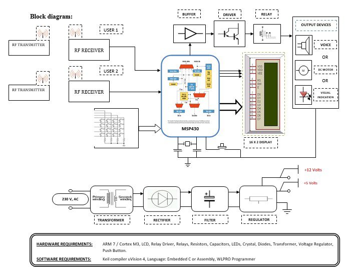
Block diagram explanation :
Power supply unit:
This section needs two voltages viz., +12 V & +5 V, as working voltages. Hence specially designed power supply is constructed to get regulated power supplies.
Buffers:
Buffers do not affect the logical state of a digital signal (i.e. a logic 1 input results in a logic 1 output whereas logic 0 input results in a logic 0 output). Buffers are normally used to provide extra current drive at the output but can also be used to regularize the logic present at an interface.
Drivers:
This section is used to drive the relay where the output is the complement of input which is applied to the drive but the current will be amplified.
Relays:
It is an electromagnetic device that is used to drive the load connected across the relay and the o/p of the relay can be connected to the controller or load for further processing.
Indicator:
This stage provides a visual indication of which relay is actuated and deactivated, by glowing respective LED or Buzzer.
MSP 430 Controllers:
The MSP430 is a mixed-signal microcontroller family from Texas Instruments. Built around a 16-bit CPU, the MSP430 is designed for low-cost and, specifically, low-power consumption embedded applications.
RF transmitter:
This is a 2-channel Radio Frequency Transmitter specially tuned with its RF Receiver part in carrier frequency. Each zone is set with one channel and transmits its presence to the moving vehicle’s RF Receiver unit.
RF receiver:
This is also a 2-channel RF Receiver specially tuned with its counterpart RF Transmitter in carrier frequency. When a vehicle enters any zone that zones RF signals are received by this unit. Thus depending upon the channel signals it receives from the transmitting end the channel output of the RF Receiver goes HIGH. This HIGH signal is fed to the ARM7 chip through Buffer & Driver and Switching stage for further processing.
Methodology:
This system presents that one RF Tx will be used for user 1, and another RF TX for user 2. Any user came. The user should enter the password that is input to the MSP430, in the controller it checks the password if the patient is authorized then it processes next. The MSP430 will generate the output that is fed to buffer IC 4050, buffer stores and given to the driver IC 2003 in driver current will amplify and voltage will invert with the help of Darlington circuit of driver IC to drive the relay. Then the signal is given to the output load, the load get turns ON.
Advantages:
- Cost efficiency.
- Integration.
- minimal losses.
- Security of supply.
Disadvantages:
The electricity network only (not gas) – it concerns both distribution and transmission levels.
Applications:
§ Mobile telephones.
§ Wireless data communications.
§ Wireless energy transfer.
§ Wireless Medical Technologies.
§ Computer interface devices.


