Table of Contents
Introduction:

The Automation of Public Service Sectors is the current trend, which transforms manpower-oriented services into semi-automatic or full automatic Sectors. As the country is opened to globalization, people’s income is rising. And the Busy world now becomes an essential part of everybody’s life. So, governments prefer not only to give quality service but also corrupt & error-free services to their citizens. As a result, this project proposed here is an advanced system, which helps Electricity Boards or Electricity Corporations to handle the Billing system smoothly. This project helps them to give quality service to its customer without any kind of problems.
Traditionally, energy monitoring has been done through electromechanical energy meters installed on various feeders and loads. This present system is not to the expected satisfaction of the energy-supplying authorities. It has many drawbacks:
- We get only the raw data.
- With available manpower, as per the records, it is not possible to prepare error-free bills.
- In the existing system, the billing for amount of energy consumed in different areas of a given city like Belgaum or Bangalore is difficult.
Modern technologies can offer much more elegant and cost-effective solutions to this need. Recording energy consumption data through current pulses is the simplest and cheapest arrangement. This project is aimed at developing a system for accurate reading and billing from a computer at Main Power Transmission And Maintains Office with data communication through the transmission line.


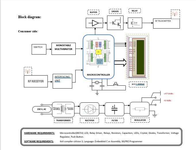
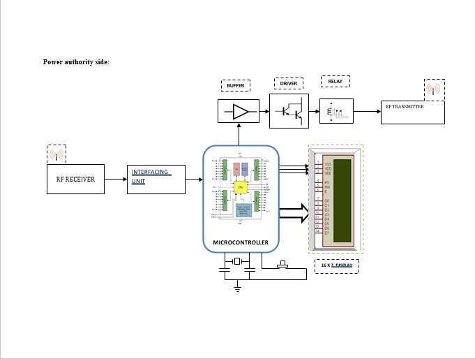
Block diagram explanation :
Power supply unit:
This section needs two voltages viz., +12 V & +5 V, as working voltages. Hence specially designed power supply is constructed to get regulated power supplies.
Microcontroller:
The 89C51 Microcontroller is the heart of this project. It is the chip that processes the User Data and executes the same. The software inherited in this chip manipulates the data and sends the result for visual display.
The general definition of a microcontroller is a single-chip computer, which refers to the fact that they contain all of the functional sections (cpu, ram, rom, i/o, ports, and timers) of a traditionally defined computer on a single integrated circuit. Some experts even describe them as special-purpose computers with several qualifying distinctions that separate them from other computers.
Features Of Microcontroller :
- 8K Bytes of In-System Reprogrammable Flash Memory
- Endurance: 1,000 Write/Erase Cycles
- Fully Static Operation: 0 Hz to 24 MHz
- Three-level Program Memory Lock
- 256 x 8-bit Internal RAM
- 32 Programmable I/O Lines
- Three 16-bit Timer/Counters
Buffers:
Buffers do not affect the logical state of a digital signal (i.e. a logic 1 input results in a logic 1 output whereas logic 0 input results in a logic 0 output). Buffers are normally used to provide extra current drive at the output but can also be used to regularize the logic present at an interface.
Drivers:
This section is used to drive the relay where the output is the complement of input which is applied to the drive but the current will be amplified.
Relays:
It is an electromagnetic device that is used to drive the load connected across the relay and the o/p of the relay can be connected to the controller or load for further processing.
Indicator:
This stage provides a visual indication of which relay is actuated and deactivated, by glowing respective LED or Buzzer.
RF transmitter:
This is a 2-channel Radio Frequency Transmitter specially tuned with its RF Receiver part in carrier frequency. Each zone is set with one channel and transmits its presence to the moving vehicle’s RF Receiver unit.
RF receiver:
This is also a 2-channel RF Receiver specially tuned with its counterpart RF Transmitter in carrier frequency. When a vehicle enters any zone that zones RF signals are received by this unit. Thus depending upon the channel signals it receives from the transmitting end the channel output of the RF Receiver goes HIGH. This HIGH signal is fed to the controller chip through Buffer & Driver and Switching stage for further processing.
Methodology:
The section explains how the ‘CENTRALIZED ELECTRICAL BILLING’ really works. The project is mainly divided into two sections: Power Authority Side and Consumer Side.
Power authority side:
This Power Authority Side section, as the name itself implies, is situated at the Power Transmission and Maintains Department’s main office. This section is kept in the Main Office of the Power Transmission and Maintains Department, where all consumer’s Electricity Bill were prepared. The PC or Computer is activated every month on a particular day to collect information on the total units consumed by every consumer within that month. The activation of the Computer as a result triggers the RF Transmitter, which sends the activation signal to the Consumer Side Section of every consumer in a one-by-one fashion. And when the Consumer Side Section gets activated and starts emitting the information packets [which contain total units consumed by that consumer], this section receives them and proceeds that information packets to Computer for further processing. The activation signal is sent to Consumer Side Section using RF Signals and Information packets are transmitted using radio signals. The implementation of two entirely different communication techniques is to prevent any false triggering and to avoid interference of signals. The Software Module takes care of the data it received and the printer prints the concerned consumers’ Monthly Electricity Bill depending on that received data. The Power supply Unit provides the necessary supply voltages for this Section.
Consumer side:
This Consumer Side Section is fitted with every Energy Meter used in that covering area, in which the Main Power Transmission and Maintains Office is situated. This section has two parts based on the activation mode: RF Receiver, which is always ON or in Active Mode and ready to receive the Activation Signal from Power Authority Side Section; and the rest of the Blocks which are initially in sleep mode and gets activated only when RF Receiver gets Activation Signal. After activation, it sends the total number of units consumed by that Consumer in the form of RF Information Signals to the Power Authority Side Section. Here one point is to be noted that even though the rest of the circuit is in sleep mode, it continuously tracks Energy Meter and keeps the number of units consumed in its memory. When this section gets activated this stored data is transmitted to Power Authority Side.
Advantages:
- Accurate meter reading and billing.
- Meter readings can be taken even under door-locked cases.
- Useful for detecting faulty and non-reading meters.
- The amount of manpower consumption is decreased considerably, and the recording of energy meter readings and preparation of bills are simplified.
- Records can be maintained for five years and is recommended to transfer the data to another storing device like a floppy disc.
- Motivation for conversation.
- For detecting tampering and theft of power.
Disadvantages:
- One-time investment cost.
Applications:
- This system is mainly developed for Electricity Board for Meter reading all consumers wirelessly.
- In Shopping malls, Industry Storerooms, and Remote Storage Banks this system can be easily implemented. The only change is instead of getting the Number of Units Consumed as data, one can get at his office the Number of goods unloaded or taken, or sold from remote area storage.
- The hill station people can use this system as their savior and sends emergency signals whenever a problem occurs.


