Table of Contents
Introduction:


Automation for Vehicles is the current trend, the project presented here is one such idea in automating the movements of important vehicles like Ambulance & Fire Fighting Vehicles, etc., here the idea is to ease the movement of an Ambulance by detecting its proximity to the hospital and displaying the arrival of the same on a display device like LCD


Block diagram explanation :
Power supply unit:
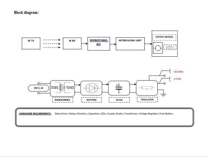
This section needs two voltages viz., +12 V & +5 V, as working voltages. Hence specially designed power supply is constructed to get regulated power supplies.
Buffers:
Buffers do not affect the logical state of a digital signal (i.e. a logic 1 input results in a logic 1 output whereas logic 0 input results in a logic 0 output). Buffers are normally used to provide extra current drive at the output but can also be used to regularize the logic present at an interface.
Drivers:
This section is used to drive the relay where the output is the complement of input which is applied to the drive but the current will be amplified.
Relays:
It is an electromagnetic device that is used to drive the load connected across the relay and the o/p of the relay can be connected to the controller or load for further processing.
Indicator:
This stage provides a visual indication of which relay is actuated and deactivated, by a glowing respective LCD or Buzzer.
Methodology:
The above block diagram shows the setup of the Auto Ambulance. This project consists of a set of IR sensors.IR transmitter is in the ambulance and the receiver is at the hospital gate .when no ambulance then at the gate side no IR signal is received. When the ambulance enters the opposite hospital gate time IR receiver receives a signal from the IR transmitter. The output of the IR receiver is fed to the interfacing unit which consists buffer, driver & relay. The buffer IC 4050, buffer stores and given to the driver IC 2003 in driver current will amplify and voltage will invert with the help of the Darlington pair circuit of driver IC to drive the relay. Then the signal is given to the load which is the gate for opening. The monostable multivibrator is for the time delay.
Advantages:
- The project is used to secure and avoid road accidents.
- This system is used to trace the culprit vehicles by police persons.
- This project can also be used by Cargo Companies to intimate their on-road vehicles about the next delivery spot or assignment.
- This system can be used for ‘timekeeping’ purposes in public transportation, such as departure & arrival timings, the number of rotations each vehicle turned, etc.
Disadvantages:
Sensor failure causes problems.
Applications:
- Automotive Applications.
- Military Applications.
- Monitoring friendly forces, equipment, and ammunition.
- Battlefield surveillance.


