Table of Contents
Introduction:

Safety is a necessary part of man’s life. Due to the accident cases reported daily on the major roads in all parts of the developed and developing countries, more attention is needed for research in designing an efficient car driving aiding system. It is expected that if such a device is designed and incorporated into our cars as road safety device, it will reduce the incidence of accidents on our roads and various premises, with a subsequent reduction in loss of life and property. However, a major area of concern for an engineer should be safety, as it concerns the use of his/her inventions and the accompanying dangers due to human limitations. When it comes to the use of a motor vehicles, accidents that have occurred over the years tell us that something needs to be done about them from an engineering point of view

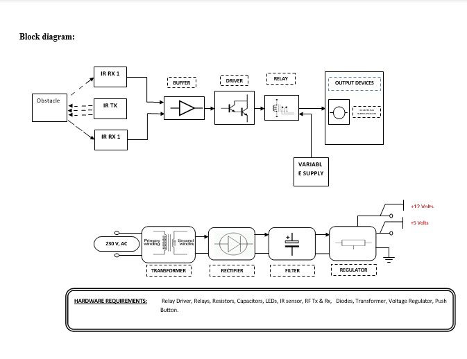
Block diagram explanation :
Power supply unit:
This section needs two voltages viz., +12 V & +5 V, as working voltages. Hence specially designed power supply is constructed to get regulated power supplies.
Buffers:
Buffers do not affect the logical state of a digital signal (i.e. a logic 1 input results in a logic 1 output whereas logic 0 input results in a logic 0 output). Buffers are normally used to provide extra current drive at the output but can also be used to regularize the logic present at an interface.
Drivers:
This section is used to drive the relay where the output is the complement of input which is applied to the drive but the current will be amplified.
Relays:
It is an electromagnetic device that is used to drive the load connected across the relay and the o/p of the relay can be connected to the controller or load for further processing.
Indicator:
This stage provides a visual indication of which relay is actuated and deactivated, by glowing respective LED or Buzzer.
IR Transmitter and Receiver:
Infrared (IR) transmitters and receivers are present in many different devices, though they are most commonly found in consumer electronics. The way this technology works is that one component flashes an infrared light in a particular pattern, which another component can pick up and translate into an instruction. These transmitters and receivers are found in remote controls and all different types of devices, such as televisions and DVD players. Peripheral devices that include this technology can also allow a computer to control various other consumer electronics. Since infrared remotes are limited to line-of-sight operation, some products can be used to extend the signals over a hardwired line or radio frequency (RF) transmissions.
Methodology:
There are two IR Receivers fitted on both sides of a single IR Transmitter. IR Receiver 1 is a normal receiver whereas IR Receiver 2 is a slightly less efficient receiver. So when IR rays transmitted by IR Transmitter hits any long-distance obstacle and come back, they are received only by IR Receiver 1. Its output goes HIGH and which in turn energizes the switching stage relay. The relay’s N/C [Normally Connected] pin supplies normal voltage to the motor from Variable Power Supply to move the vehicle at normal speed. When the relay gets energizes then N/O {Normally Open] pins come into action and supply Low voltage from Variable Power Supply to run the motor at low speed. Thus vehicle reduces its speed when any obstacle is observed in front of the vehicle at a safe distance.
When an obstacle comes very near then IR rays transmitted by IR Transmitter are detected by a less efficient IR Receiver 2. Thus its output goes HIGH and which in turn energizes the switching stage relay. This relay’s N/C pins are in a series of power supply lines of the motor and hence motor is running at low speed when an obstacle is detected at a safe distance. When an obstacle is very near the relay gets energizes and contacts changes. This contact change breaks the power supply line of the motor and hence the motor stops running. Thus vehicle stops when an obstacle is very near to it.
Advantages:
- The driver is alerted of a possible collision for a considerable amount of time before it occurs.
- Effective in implementation.
- Low power consumption, and compact size,
- High reliability, due to the usage of power semiconductor devices.
Disadvantages:
- Operative and maintenance are cost-effective.
- Initial and maintenance cost is high.
Applications:
- Adaptive cruise control.
- Anti-collision devices.


