Table of Contents
Introduction:


Single Phase and Three Phase Induction machines are very popular in industries because of their vast applications. Hence it becomes necessary to protect them against faults to ensure uninterrupted operation and functioning. Various parameter monitoring systems are there for other types of machines, but in the case of induction machines,s the monitoring systems are not extensively used due to the high cost of installation and physical constraints. To overcome the limitations in monitoring, Zigbee Based System is used which makes it cost-effective and simple on the other hand2. To start with, first, we should know what Zigbee Protocol is. Zigbee is a wireless communication device like Bluetooth and Wireless Local Area Network (WLAN)3. The basic difference between Zigbee and other communication protocols is that all Zigbee devices relay each other’s traffic, bypassing the wired network entirely. While Bluetooth devices connect to another wireless that acts as a hub and WLAN devices connect directly to an access point, which is wired to the enterprise network using Ethernet.
The Institute of Electrical and Electronics Engineers (IEEE) developed 802.15.4 standards and helped the production of the Zigbee protocol and devices that support this protocol. The disadvantage of using traditional systems is that it increases the cost whereas digital systems reduce the cost of the system. The basic structure of Zigbee-based parameter monitoring and the controlling system consists of a microcontroller board and ZigBee device, one set of microcontroller boards and ZigBee device are near the induction machine and acts as a transmitter for the other microcontroller and ZigBee device which is near the computer where the parameters are displayed on a computer using software application. In addition to Zigbee Device various other sensors are used.


Block diagram explanation :
Power supply unit:
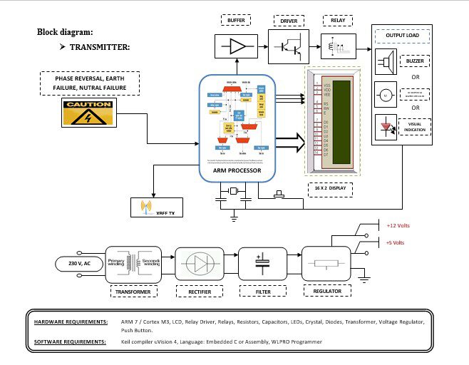
This section needs two voltages viz., +12 V & +5 V, as working voltages. Hence specially designed power supply is constructed to get regulated power supplies.
ARM processor:
ARM is a computer processor-based RISC architecture. A RISC-based computer design approach means ARM processors require significantly fewer transistors than typical processors in average computers. This approach reduces costs, heat, and power use. The low power consumption of ARM processors has made them very popular:
The ARM architecture (32-bit) is the most widely used in mobile devices, and the most popular 32-bit one in embedded systems.
ARM processor features include:
- Load/store architecture.
- An orthogonal instruction set.
- Mostly single-cycle execution.
- A 16×32-bit register
- Enhanced power-saving design.
Zigbee technology:
ZigBee is the name of a specification for a suite of high-level communication protocols using small, low-power digital radios based on the IEEE 802.15.4 standard for wireless personal area networks (WPANs).
- A very low-cost, low power consumption two-way, wireless communication standard for automation, toys & PC peripherals.
- Low power consumption: 6 months to 5 years battery life for most applications.
- Low cost: At least half the cost of Bluetooth solutions.
- The high density of nodes per network: 250 nodes per network, multiple co-located networks.Data rate requirements: Few bits to 250kbps sufficient.
Buffers:
Buffers do not affect the logical state of a digital signal (i.e. a logic 1 input results in a logic 1 output whereas logic 0 input results in a logic 0 output). Buffers are normally used to provide extra current drive at the output but can also be used to regularize the logic present at an interface.
Drivers:
This section is used to drive the relay where the output is the complement of input which is applied to the drive but the current will be amplified.
Relays:
It is an electromagnetic device that is used to drive the load connected across the relay and the o/p of the relay can be connected to the controller or load for further processing.
Indicator:
This stage provides a visual indication of which relay is actuated and deactivated, by glowing respective LED or Buzzer.
Methodology:
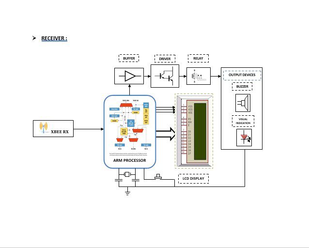
This section gives an overview of the monitoring scheme of the induction machine. A general block diagram of the proposed scheme is given in the block diagram. A General Block Diagram of Monitoring Scheme. The whole system is divided into two parts- transmitter and receiver. In the transmitter part a network of sensors and used to monitor the risky parameters such as phase, Neutral, Earth, and reversal of the induction machine present at the plant location. The monitoring data is simultaneously fed to the ARM. This data is transmitted efficiently and smoothly to the receiver end through wireless Zigbee Communication Protocol (IEEE802.15.4 Standards). The micro-controller at the transmitter end is so programmed that if the monitoring parameters of the induction machine come out of the desired or safety limit, a signal will be generated by the ARM which will energize the relay circuit and the contractor cuts the mains supply to the data received at the receiver end is transferred to ARM. Thus continuous monitoring of the parameters of the induction machine can be done from a remote location far away from the actual working location.
Advantages:
- Cost efficiency.
- In this project losses are minimal.
- This project can implement for the Security of supply.
Disadvantages:
- The electricity network only (not gas) concerns both distribution and transmission levels.
- It increases the cost whereas digital systems reduce the cost of the system.
Applications:
- This project can be implemented for Health Care.
- This project can be implemented in Home Automation.
- For Security services, we can use this project.
- Communication and device discovery.
- In Industrial applications.


