Table of Contents
Introduction:


MOBILE robot navigation has stood as an open and challenging problem over the last few decades. Despite the significant advances in this field, researchers have yet to reach a comfortable level of satisfaction. To date, most of the robot navigation algorithms proposed in the literature are either tailored toward particular structured environments or driven by an overwhelming degree of computational complexity. In some cases, the hardware needed to implement the algorithm can be more costly than the robot itself. This makes the practical realization of such algorithms in most real-world robotic systems questionable. This paper contributes to the efforts of developing practical, modular, and easy-to-implement robot navigation algorithms that are both cost and computationally effective. The proposed algorithm takes advantage of the emerging Zigbee technology and a fuzzy logic controller (FLC) to guide the robot to navigate in its working space given these shortcomings, researchers shifted their interest to vision-based navigation to improve the robot position estimation by tracing the visual features in the environment and using them as landmarks. This measurement usually returns bearing to the visual features only, with no a priori knowledge of the landmark positions. Nevertheless, such a technique also has its disadvantages, which include the lack of information depth, complex image processing algorithms with high computational burden, and its dependence on the working environment. This problem can be alleviated by adopting behavior-based navigation systems, as they can incorporate a relatively large number of sensors, making them suitable for navigation in unstructured environments. However, relying on numerous sensors makes the system vulnerable to drifts and cumulative errors. To overcome this shortcoming, some researchers used artificial landmarks to compensate for these errors. a novel navigation technique in which Zigbee protocol to control the robot and also to get the live view we are going to use a camera that is highly integrated one from which we can see the images at night also i.e. using a night vision camera.


Block diagram explanation :
Power supply unit:
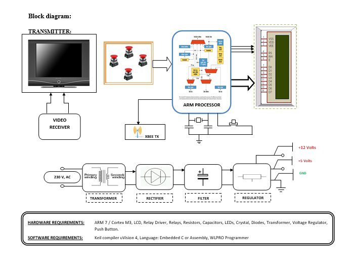
This section needs two voltages viz., +12 V & +5 V, as working voltages. Hence specially designed power supply is constructed to get regulated power supplies.
ZigBee technology:
Zigbee is the name of a specification for a suite of high-level communication protocols using small, low-power digital radios based on the IEEE 802.15.4 standard for wireless personal area networks (WPANs).
- Very low cost, low power consumption two-way, wireless communication standard for automation, toys & PC peripherals.
- Low power consumption: 6 months to 5 years battery life for most applications.
- Low cost: At least half the cost of Bluetooth solutions.
- The high density of nodes per network: 250 nodes per network, multiple co-located networks.Data rate requirements: Few bits to 250kbps sufficient.
ARM processor:
ARM is a computer processor-based RISC architecture. A RISC-based computer design approach means ARM processors require significantly fewer transistors than typical processors in average computers. This approach reduces costs, heat, and power use. The low power consumption of ARM processors has made them very popular:
The ARM architecture (32-bit) is the most widely used in mobile devices, and the most popular 32-bit one in embedded systems.
ARM processor features include:
- Load/store architecture.
- An orthogonal instruction set.
- Mostly single-cycle execution.
- A 16×32-bit register
- Enhanced power-saving design.
Night vision Camera:
It is the ability to see in low-light conditions. Whether by biological or technological means, night vision is made possible by a combination of two approaches: sufficient spectral range, and sufficient intensity range. Humans have poor night vision compared to many animals, in part because the human eye lacks a tapetum lucidum.
Buffers:
Buffers do not affect the logical state of a digital signal (i.e. a logic 1 input results in a logic 1 output whereas logic 0 input results in a logic 0 output). Buffers are normally used to provide extra current drive at the output but can also be used to regularize the logic present at an interface.
Drivers:
This section is used to drive the relay where the output is the complement of input which is applied to the drive but the current will be amplified.
Relays:
It is an electromagnetic device that is used to drive the load connected across the relay and the o/p of the relay can be connected to the controller or load for further processing.
Indicator:
This stage provides a visual indication of which relay is actuated and deactivated, by glowing respective LED or Buzzer.
Methodology:
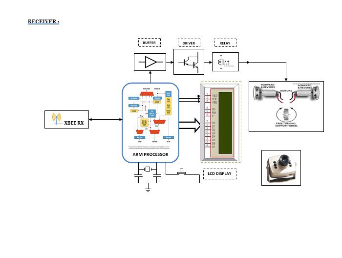
A block diagram which is shown above is divided into two parts that are transmitter and receiver. The transmitter part is which is in the base station and can be controlled from a remote area using ZIGBEE as a communication protocol. The person at the transmitting end controls the robot of the remote areas using key inputs along with that he can view the situation at the war field here we use a special camera in which we can get the images at night time.
Advantages:
- Wireless control
- Surveillance System.
- Vehicle Navigation with the use of 3G technology.
- Takes in use of mobile technology which is almost available everywhere.
- This wireless device has no foundation of range and can be controlled as far as a network of cell phones.
Disadvantages:
- In this project usage of relays leads to consuming more power.
Applications:
- The main purpose for designing this robot is to implement it in the defense sector to sense humans and detect weapons/bombs with the human or buried in a place where humans cannot fetch them.
- The sensors with smaller range frequencies are sufficient to install this robot in residents.
- The sensors with very high frequencies are required to install this robot in the IT industries
- This robot can be installed in banks, especially in the places where jewels are kept (locker area).
- In educational institutions, this robot can play a vital role in the areas of libraries and laboratories where valuable equipment is kept.


