Table of Contents
Introduction:


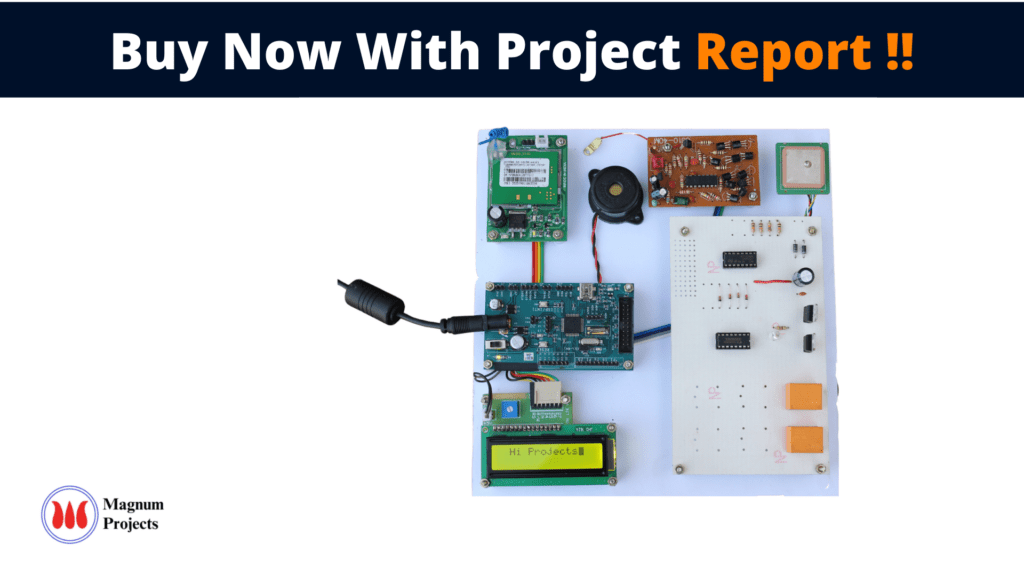
The vehicle tracking system is used in a wide variety of applications. Most of the tracking systems use geographic position and time information from global positioning satellites. GSM(Global System of Mobile Communications) and GPS(Global Positioning System) based vehicle location and tracking systems will provide effective, real-time vehicle location, mapping, and reporting. It also provides the most up-to-date information about the ongoing trips. This system incorporates a hardware device (GPS receivers) installed in the bus. The GPS unit placed in the bus receives signals from any four visible satellites among the constellation of satellites in space. The GPS unit consists of a receiver, a controller/processing unit, and a communication interface. The basic function of the device in the bus is to acquire and transmit the position of the bus to the concerned person or office at a fixed interval of time. The ARM forms the heart of the tracking unit, which acquires and processes the position data from the GPS module. The communication interface is responsible for receiving the signals from the satellites and sending the information to the concerned person or office.


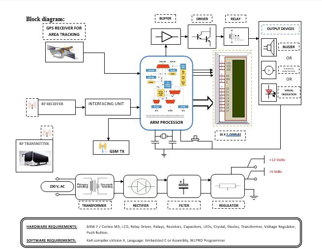
Block diagram explanation :
Power supply unit:
This section needs two voltages viz., +12 V & +5 V, as working voltages. Hence specially designed power supply is constructed to get regulated power supplies.
GPS module:
This is a GPS Receiver (5V Serial) with high gain having 4 Pin 2.54mm pitch strip. The third-generation POT (Patch Antenna on Top) is used by the receiver for the GPS module. It can be interfaced with normal 5V ARM7 with the help of the in-built 3V-5V converter. The interfacing is made easier with the help of a low pin count (4-pin) strip. The 4 Pins are 5V, TX, RX, and GND. This standalone 5V GPS Module does not require external components. It consists of an internal RTC Back up battery and can be directly connected to the USART of the ARM7.
The current date, time, longitude, latitude, altitude, speed, and travel direction / heading among other data, are provided by the module and can be used in many applications including navigation, fleet management, tracking systems, mapping, and robotics. The module can support up to 51 channels. The GPS solution enables small form factor devices which deliver major advancements in GPS performance, accuracy, integration, computing power, and flexibility. They are used to simplify the embedded system integration process.
GSM:
GSM Shield (SIM 900a): The SIM900 which is a complete Quad-band GSM/GPRS solution comes in a SMT module that can be embedded in customer applications. Featuring an industry-standard interface, the SIM900 delivers GSM/GPRS 850/900/1800/1900MHz performance for Data, voice, SMS, and Fax in a small form factor and with low power consumption. SIM900 can fit almost all the space requirements in the M2M application with dimensions of 24mm x 24mm x 3 mm. SIM900 is designed with a very powerful single-chip processor integrating AMR926EJ-S core. Quad-band GSM/GPRS module with a size of 24mmx24mmx3mm, SMT type suit for customer application, An embedded Powerful TCP/IP protocol stack Based upon the mature and field-proven platform, backed up by our support service, from definition to design and production.
NOTE: Modem may change.
ARM processor:
ARM is a computer processor-based RISC architecture. A RISC-based computer design approach means ARM processors require significantly fewer transistors than typical processors in average computers. This approach reduces costs, heat, and power use. The low power consumption of ARM processors has made them very popular:
The ARM architecture (32-bit) is the most widely used in mobile devices, and the most popular 32-bit one in embedded systems.
ARM processor features include:
- Load/store architecture.
- An orthogonal instruction set.
- Mostly single-cycle execution.
- A 16×32-bit register
- Enhanced power-saving design.
Buffers:
Buffers do not affect the logical state of a digital signal (i.e. a logic 1 input results in a logic 1 output whereas logic 0 input results in a logic 0 output). Buffers are normally used to provide extra current drive at the output but can also be used to regularize the logic present at an interface.
Drivers:
This section is used to drive the relay where the output is the complement of input which is applied to the drive but the current will be amplified.
Relays:
It is an electromagnetic device that is used to drive the load connected across the relay and the o/p of the relay can be connected to the controller or load for further processing.
Indicator:
This stage provides a visual indication of which relay is actuated and deactivated, by glowing respective LED or Buzzer.
RF transmitter:
This is a 2-channel Radio Frequency Transmitter specially tuned with its RF Receiver part in carrier frequency. Each zone is set with one channel and transmits its presence to the moving vehicle’s RF Receiver unit.
RF receiver:
This is also a 2-channel RF Receiver specially tuned with its counterpart RF Transmitter in carrier frequency. When a vehicle enters any zone that zones RF signals are received by this unit. Thus depending upon the channel signals it receives from the transmitting end the channel output of the RF Receiver goes HIGH. This HIGH signal is fed to the ARM7 chip through Buffer & Driver and Switching stage for further processing.
Methodology:
For any Bus detection device for the passengersystem to work a mechanism to determine the bus location and a location display mechanism is required. The proposed model can be broken down into two basic components:
- A Location Display Components.
- The Location Identification Components.
In the above block diagram, we can see that the complete setup is for a Bus detection device for the passengersystem, in our project, we are monitoring the bus location with the help of GPS and sending the SMS to the concerned person or office. In Bus RF Tx & GPS, well placed, RF Tx will transmit signal continuously and when the bus reaches a particular stop there receiver receives the RF signal from the. At the same time, the GPS module reads coordinates and sends them to the concerned person’s number which is stored in ARM with the help of GSM which is connected to ARM.
Advantages:
- The freely available GPS develops several applications which are used to make transportation services easier for transport management centers, drivers, and passengers.
- Fleet monitoring.
- Vehicle scheduling
- Route monitoring.
- Driver monitoring.
- Accident analysis.
- Geo-fencing geo-coding.
Disadvantages:
- This program is highly sensitive to the environment.
Applications:
- Business process.
- Warehouse and routing.
- The project is used to secure and avoid road accidents.
- It can be used as part of the automation of s or Public Transportation.
- This system is used to trace the culprit vehicles by police persons.
- This system can be used for ‘timekeeping’ purposes in public transportation, such as departure & arrival timings, the number of rotations each vehicle turned, etc.


