Table of Contents
Introduction:


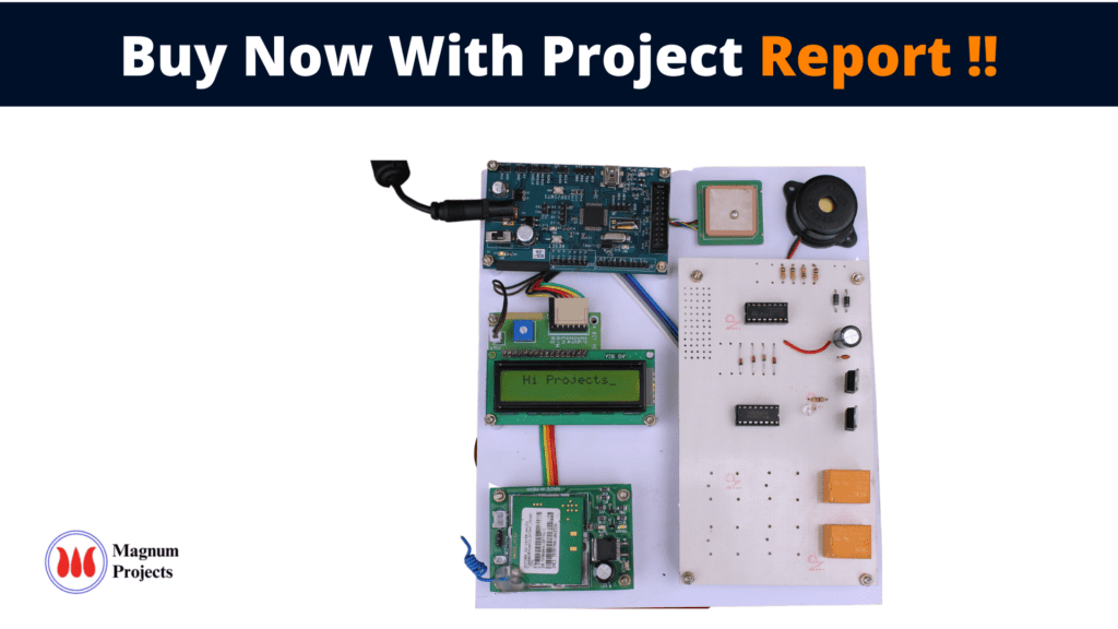
TheProposed design is cost-effective, reliable, and has the function of accurate tracking. When large objects or vehicles were spread out over the ground, the owner corporations often found it difficult to keep track of what was happening. They required some type of system to determine where each object was at any given time and for how long it traveled. Also the need for tracking in consumer’s vehicle use to prevent any kind of theft because police can use tracking reports to locate stolen vehicle. GSM and GPS-based tracking systems will provide effective, real-time vehicle location, and reporting. A GPS-GSM-based tracking system will inform you where your vehicle is and where it has been, how long it has been. The system uses geographic position and time information from the Global Positioning Satellites. The system has an “On-Board Module” which resides in the vehicle to be tracked. The On-Board module consists of a GPS receiver, a GSM modem, and an ARM processor. It can provide telemonitoring.
This proposed work is an attempt to design a tracking unit that uses the global positioning system to determine the precise location of an object, person, or other asset to which it is attached, and using a GSM modem this information can be transmitted to remote users. It can provide a telemonitoring system for inter-cities vehicles such as taxis and buses. This system contains a single-board embedded system that is equipped with GPS and GSM modems along with an ARM processor that is installed in the vehicle. During object motion, its location can be reported by SMS message. A software package is developed to read, process, analyze and store incoming SMS messages. The use of GSM and GPS technologies allows the system to track objects and provides the most up-to-date information about ongoing trips. If a password like SMS is sent by the owner, it automatically stops the vehicle or we can use it for different other work, it can provide real-time control. The current system can be able to provide a monitoring process from anywhere.


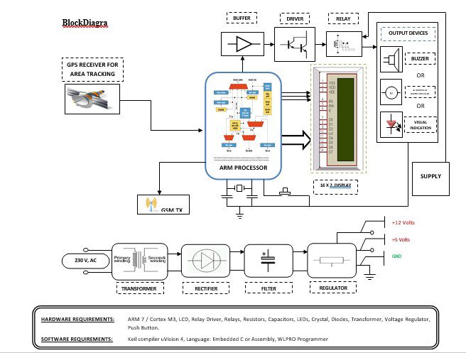
Block diagram explanation
Power supply unit
This section needs two voltages viz., +12 V & +5 V, as working voltages. Hence specially designed power supply is constructed to get regulated power supplies.
GPS module:
This is a GPS Receiver (5V Serial) with high gain having 4 Pin 2.54mm pitch strip. The third-generation POT (Patch Antenna on Top) is used by the receiver for the GPS module. It can be interfaced with normal 5V ARM7 with the help of the in-built 3V-5V converter. The interfacing is made easier with the help of a low pin count (4-pin) strip. The 4 Pins are 5V, TX, RX, and GND. This standalone 5V GPS Module does not require external components. It consists of an internal RTC Back up battery and can be directly connected to the USART of the ARM7.
The current date, time, longitude, latitude, altitude, speed, and travel direction / heading among other data, are provided by the module and can be used in many applications including navigation, fleet management, tracking systems, mapping, and robotics. The module can support up to 51 channels. The GPS solution enables small form factor devices which deliver major advancements in GPS performance, accuracy, integration, computing power, and flexibility. They are used to simplify the embedded system integration process.
GSM:
GSM Shield (SIM 900a): The SIM900 which is a complete Quad-band GSM/GPRS solution comes in a SMT module that can be embedded in customer applications. Featuring an industry-standard interface, the SIM900 delivers GSM/GPRS 850/900/1800/1900MHz performance for Data, voice, SMS, and Fax in a small form factor and with low power consumption. SIM900 can fit almost all the space requirements in the M2M application with dimensions of 24mm x 24mm x 3 mm. SIM900 is designed with a very powerful single-chip processor integrating AMR926EJ-S core. Quad-band GSM/GPRS module with a size of 24mmx24mmx3mm, SMT type suit for customer application, An embedded Powerful TCP/IP protocol stack Based upon the mature and field-proven platform, backed up by our support service, from definition to design and production.
ARM processor
ARM is a computer processor-based RISC architecture. A RISC-based computer design approach means ARM processors require significantly fewer transistors than typical processors in average computers. This approach reduces costs, heat, and power use. The low power consumption of ARM processors has made them very popular:
The ARM architecture (32-bit) is the most widely used in mobile devices, and the most popular 32-bit one in embedded systems.
Buffers
Buffers do not affect the logical state of a digital signal (i.e. a logic 1 input results in a logic 1 output whereas logic 0 input results in a logic 0 output). Buffers are normally used to provide extra current drive at the output but can also be used to regularize the logic present at an interface
Drivers
This section is used to drive the relay where the output is the complement of input which is applied to the drive but the current will be amplified.
Relays
It is an electromagnetic device that is used to drive the load connected across the relay and the o/p of the relay can be connected to the controller or load for further processing.
Buzzer:
A buzzer or beeper is an audio signaling device, which may be mechanical, electromechanical, or piezoelectric. Typical uses of buzzers and beepers include alarm devices, timers, and confirmation of user input such as a mouse click or keystroke.
DC motor:
A DC motor relies on the fact that magnet poles repel and unlike magnetic poles attract each other. A coil of wire with a current running through it generates an electromagnetic field aligned with the center of the coil. By switching the current on or off in a coil its magnetic field can be switched on or off or by switching the direction of the current in the coil the direction of the generated magnetic field can be switched 180°.
Indicator:
This stage provides a visual indication of which relay is actuated and deactivated, by glowing respective LED or Buzzer.
Methodology:
This module consists of an accident alert system, GPS Module, GSM Module, ARM controller unit, and the output. If the vehicle has this module, then every time wherever it’s going all information will be sent to the caretaker Via GPS and GSM. Here GPS receiver each every time receives the coordinates of the location from the satellite and sends that to the ARM controller. The ARM controller analyses the signal and sends the same information to the caretaker via the GSM module. If something happens wrong ARM controller will activate the buzzer.
Advantages:
- Easy to use for rural areas.
- Automated areas.
- Low power consumption.
- Flexible and reliable.
- This application is easy to install and easy to operate.
- More reliable than manual Operation.
- In this project losses are Minimal.
- This project can implement for the Security of supply.
- Automatically controlled & Easy to use.
Disadvantages:
- It increases the cost whereas digital systems reduce the cost of the system.
- High Cost.
Applications:
- This system finds its application in real-time traffic surveillance. It could be used as a valuable tool for real-time travelers.
- This system can be implemented in industries.
- We can implement this project in all vehicles.
- Where security is important there we can implement this project.
- Without much change in the circuit; it can be used with any 4-wheeler.


