Table of Contents
Introduction:


Electricity is an extremely handy and useful form of energy. It plays an ever-growing role in our modern industrialized society. The electrical power systems are highly non-linear, extremely huge, and complex networks. Such electric power systems are unified for economic benefits, increased reliability, and operational advantages. They are one of the most significant elements of both national and global infrastructure, and when these systems collapse it leads to major direct and indirect impacts on the economy and national security. A power system consists of components such as generators, lines, transformers, loads, switches, and compensators. However, widely dispersed power sources and loads are the general configuration of modern power systems. For many applications, it is necessary to disable a DC-DC converter when its input voltage goes outside a specified range. A transformer is a static electrical device used in electric power systems to transfer power between circuits through the use of electromagnetic induction. Transformers are devices that transfer energy from one circuit to another utilizing a common magnetic field. When an alternating current flows in a conductor, a magnetic field exists around the conductor. If another conductor is placed in the field created by the first conductor such that the flux lines link the second conductor, then a voltage is induced into the second conductor. The use of a magnetic field from one coil to induce a voltage into a second coil is the principle on which transformer theory and application are based. Transformers range in size from thumbnail-sized used in microphones to units weighing hundreds of tons interconnecting the power grid. A wide range of transformer designs are used in electronic and electric power applications. Transformers are essential for the transmission, distribution, and utilization of electrical energy


Block diagram explanation
Power supply unit
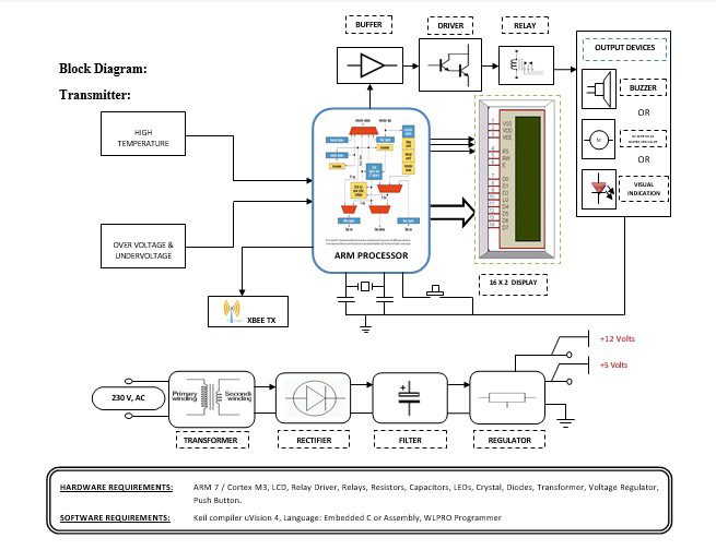
This section needs two voltages viz., +12 V & +5 V, as working voltages. Hence specially designed power supply is constructed to get regulated power supplies.
Over voltage and under voltage:
When the voltage in a circuit or part of it is raised above its upper design limit, this is known as overvoltage.
ARM processor
ARM is a computer processor-based RISC architecture. A RISC-based computer design approach means ARM processors require significantly fewer transistors than typical processors in average computers. This approach reduces costs, heat, and power use. The low power consumption of ARM processors has made them very popular:
The ARM architecture (32-bit) is the most widely used in mobile devices, and the most popular 32-bit one in embedded systems.
Buffers
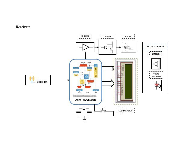
Buffers do not affect the logical state of a digital signal (i.e. a logic 1 input results in a logic 1 output whereas logic 0 input results in a logic 0 output). Buffers are normally used to provide extra current drive at the output but can also be used to regularize the logic present at an interface.
Drivers
This section is used to drive the relay where the output is the complement of input which is applied to the drive but the current will be amplified.
Relays
It is an electromagnetic device that is used to drive the load connected across the relay and the o/p of the relay can be connected to the controller or load for further processing.
Buzzer:
A buzzer or beeper is an audio signaling device, which may be mechanical, electromechanical, or piezoelectric. Typical uses of buzzers and beepers include alarm devices, timers, and confirmation of user input such as a mouse click or keystroke.
DC motor:
A DC motor relies on the fact that magnet poles repel and unlike magnetic poles attracts each other. A coil of wire with a current running through it generates an electromagnetic field aligned with the center of the coil. By switching the current on or off in a coil its magnetic field can be switched on or off or by switching the direction of the current in the coil the direction of the generated magnetic field can be switched 180°.
Indicator:
This stage provides a visual indication of which relay is actuated and deactivated, by glowing respective LED or Buzzer.
Methodology:
Distributed transformers are prone to damage due to overload or huge current flows through the internal winding of the transformer. The transformers are to be monitored very cautiously during these situations. The proposed system consists of a monitoring unit that is connected to the distribution transformer to monitor the same. We have designed a system based on ARM controller LPC2148 that monitors and controls the voltage of a distribution transformer present in a substation. The monitored output will be sent to the Lineman at the main station which is at a remote place, through Zigbee. The parameters (High temperature, over-voltage, and under-voltage) monitored at the distribution transformer are compared with the rated values of the transformer. The software in the ARM compares the received values with the rated measurements of the distribution transformer and shuts down the transformer so that it can be prevented damage and Performances can be enhanced quite to a remarkable level.
Advantages:
1. Cost efficiency.
2. In this project losses are Minimal.
3. This project can implement for the Security of supply.
Disadvantages:
1. The electricity network only (not gas) concerns both distribution and transmission levels.
2. It increases the cost whereas digital systems reduce the cost of the system.
Applications:
1. This system can be implemented in industries.
2. This system can be used to monitor and control the home appliances


