Table of Contents
Introduction:

The idea of designing a new system for the streetlight that does not consume a huge amount of electricity and illuminates large areas with the highest intensity of light is concerning each engineer working in this field. Providing street lighting is one of the most important and expensive responsibilities of a city. Lighting can account for 10–38% of the total energy bill in typical cities worldwide. Street lighting is a particularly critical concern for public authorities in developing countries because of its strategic importance for economic and social stability. Inefficient lighting wastes significant financial resources every year, and poor lighting creates unsafe conditions. Energy-efficient technologies and design mechanisms can reduce cost of the street lighting drastically.
Manual control is prone to errors and leads to energy wastages and manually dimming at midnight is impracticable. Also, dynamically tracking the light level is manually impracticable. The current trend is the introduction of automation and remote management solutions to control street lighting. There are various numbers of control strategies and methods in controlling the street light system such as the design and implementation of a CPLD-based solar power saving system for street lights and automatic traffic controllers, the design and fabrication of automatic street light control systems, automatic street light intensity control, and road safety module using the embedded system, automatic street light control system [5], Intelligent Street Lighting System Using Gsm, energy consumption saving solutions based on intelligent street lighting control system and A Novel Design of an Automatic Lighting Control System for a Wireless Sensor Network with Increased Sensor Lifetime and Reduced Sensor Numbers. In this paper, two kinds of sensors will be used which are light sensors and photoelectric sensors. The light sensor will detect darkness to activate the ON/OFF switch, so the streetlights will be ready to turn on and the photoelectric sensor will detect movement to activate the streetlights. LDR, which varies according to the amount of light falling on its surface, gives inductions for whether it is a day-night time, the photoelectric sensors are placed on the side of the road, which can be controlled by a microcontroller.

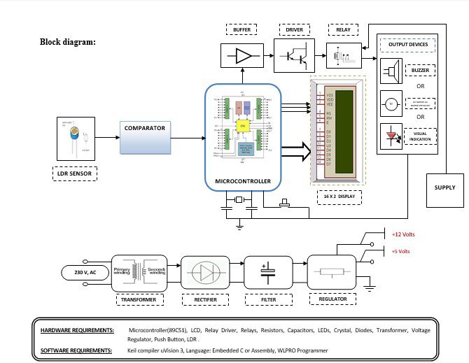
Block diagram explanation :
Power supply unit:
This section needs two voltages viz., +12 V & +5 V, as working voltages. Hence specially designed power supply is constructed to get regulated power supplies.
Buffers:
Buffers do not affect the logical state of a digital signal (i.e. a logic 1 input results in a logic 1 output whereas logic 0 input results in a logic 0 output). Buffers are normally used to provide extra current drive at the output but can also be used to regularize the logic present at an interface.
Comparator:
This part reads the user card, if found valid then it processes next. This card automatically recognizes the privilege level. The heart of this card reader is the popular Operational Amplifier IC. Here every card offers some unique amount of resistance to the card reader block. Depending upon the resistance the card offers, the card reader comes to know what privilege the cardholder got.
Microcontroller:
The 89C51 Microcontroller is the heart of this project. It is the chip that processes the User Data and executes the same. The software inherited in this chip manipulates the data and sends the result for visual display.
The general definition of a microcontroller is a single-chip computer, which refers to the fact that they contain all of the functional sections (cpu, ram, rom, i/o, ports, and timers) of a traditionally defined computer on a single integrated circuit. Some experts even describe them as special-purpose computers with several qualifying distinctions that separate them from other computers.
Features Of Microcontroller :
- 8K Bytes of In-System Reprogrammable Flash Memory
- Endurance: 1,000 Write/Erase Cycles
- Fully Static Operation: 0 Hz to 24 MHz
- Three-level Program Memory Lock
- 256 x 8-bit Internal RAM
- 32 Programmable I/O Lines
- Three 16-bit Timer/Counters
Drivers:
This section is used to drive the relay where the output is the complement of input which is applied to the drive but the current will be amplified.
Relays:
It is an electromagnetic device that is used to drive the load connected across the relay and the o/p of the relay can be connected to the controller or load for further processing.
Indicator:
This stage provides a visual indication of which relay is actuated and deactivated, by glowing respective LED or Buzzer.
LDR Sensor:
A light-dependent resistor, alternatively called an LDR, photoresistor, photoconductor, or photocell, is a variable resistor whose value decreases with increasing incident light intensity.
An LDR is made of a high-resistance semiconductor. If light falling on the device is of high enough frequency, photons absorbed by the semiconductor give bound electrons enough energy to jump into the conduction band. The resulting free electron (and its hole partner) conduct electricity, thereby lowering resistance.
Methodology:
When we want to turn the ON or OFF the Street lights using an LDR sensor, in the day time light falls on LDR intensity of light is more so the resistance of LDR decreases. The output signal is fed comparator it compares in the comparator and then given to the microcontroller. The microcontroller generates the output put that is fed to buffer IC 4050, buffer stores and given to the driver IC 2003 in driver current will amplify and voltage will invert with the help of the Darlington pair circuit of driver IC to drive the relay. Then the signal is given to the output load to turn ON the lights or turn OFF the lights. Depending upon the intensity of light varies in the resistance of LDR which will compare in comparator and turn ON the lights and control the intensity of lights in the day, evening, and night time.
Advantages:
- The circuit is very useful when you want to operate appliances kept at your home, sitting in your office.
- It can be used in industries for remote operation of devices.
Disadvantages:
Sensor failure can cause problems.
.Applications:
- Home Applications.
- Offices.


