

Table of Contents
Introduction:
In this sophisticated world, every activity is getting atomized with the help of electronic concepts. All the way so far we have seen that any controlling of parameters, measuring as well as testing of circuits or components is carried out with analog instruments. So we decided to develop a Microcontroller aid that is helpful for the above purpose which is called Digital based illumination control.
The ‘Digital-based illumination control’ project described here is a novel approach to control the intensity of the Bulb automatically. This system is very useful in the summer seasons, as during that light requirements are crucial. Since the available power source is limited, due to lack of water storage, it is advisable to use the available resources effectively. So this system controls the room’s intensity of Bulb is controlled by the darkness of the room and hence prevents unnecessary power wastage. One more additional feature is: whenever human presence is detected in the room then only the bulb puts ON.
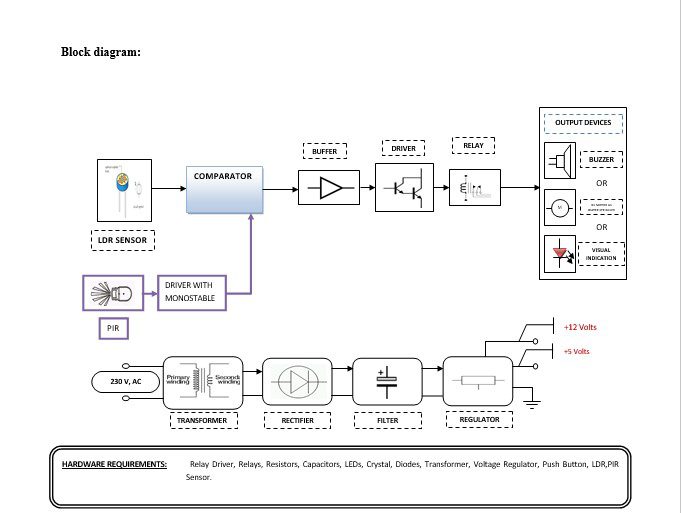
Block diagram explanation :
Power supply unit:
This section needs two voltages viz., +12 V & +5 V, as working voltages. Hence specially designed power supply is constructed to get regulated power supplies.
Comparator:
This part reads the user card, if found valid then it processes next. This card automatically recognizes the privilege level. The heart of this card reader is the popular Operational Amplifier IC. Here every card offers some unique amount of resistance to the card reader block. Depending upon the resistance the card offers, the card reader comes to know what privilege the cardholder got.
PIR Sensor:
The space to be monitored is divided by the lens into several zones. The number of zones depends on the number of segments of which the lens is composed. When somebody moves from one zone to another, there is a temperature change which is collected by the lens as a variation in radiant energy. As the focus of the lens is a hydroelectric sensor that reacts to such a change by generating a small electric signal. That signal is processed and used to actuate/deactivate the appliances.
Buffers:
Buffers do not affect the logical state of a digital signal (i.e. a logic 1 input results in a logic 1 output whereas logic 0 input results in a logic 0 output). Buffers are normally used to provide extra current drive at the output but can also be used to regularize the logic present at an interface.
Drivers:
This section is used to drive the relay where the output is the complement of input which is applied to the drive but the current will be amplified.
Relays:
It is an electromagnetic device that is used to drive the load connected across the relay and the o/p of the relay can be connected to the controller or load for further processing.
Indicator:
This stage provides a visual indication of which relay is actuated and deactivated, by glowing respective LED or Buzzer.
LDR Sensor:
A light-dependent resistor, alternatively called an LDR, photoresistor, photoconductor, or photocell, is a variable resistor whose value decreases with increasing incident light intensity.
An LDR is made of a high-resistance semiconductor. If light falling on the device is of high enough frequency, photons absorbed by the semiconductor give bound electrons enough energy to jump into the conduction band. The resulting free electron (and its hole partner) conduct electricity, thereby lowering resistance.
Methodology:
When we want to turn ON or OFF the lights in a room using an LDR sensor, in the daytime light falls on LDR intensity of light is more so the resistance of LDR decreases. The output signal is fed comparator it compares in the comparator. The comparator compares intensity according to that generates the output put that is fed to buffer IC 4050, buffer stores and given to the driver IC 2003 in driver current will amplify and voltage will invert with the help of Darlington pair circuit of driver IC to drive the relay. Then the signal is given to the output load to turn ON the lights or turn OFF the lights. Depending upon the intensity of light varies in the resistance of LDR which will compare in the comparator and turn ON the lights and control the intensity of lights in the day, evening, and nighttime. The whole process is carried out when the PIR sensor detects the movement of the person .when the person enters the home then only the comparator generates the output to turn the ON or OFF the lights.
Advantages:
- The circuit is very useful when you want to operate appliances kept at your home, sitting in your office.
- It can be used in industries for remote operation of devices.
Disadvantages:
Sensor failure can cause problems.
Applications:
- Home Applications.
- Offices.
- Industries.