Table of Contents
Introduction:

With the increasing levels of technology, the efforts being put to produce any kind of work have been continuously decreasing. The efforts required in achieving the desired output can be effectively and economically decreased by the implementation of better designs.
Power screws are used to convert rotary motion into translator motion. A screw jack is an example of a power screw in which a small force applied in a horizontal plane is used to raise or lower a large load. The principle on which it works is similar to that of an inclined plane. The mechanical advantage of a screw jack is the ratio of the load applied to the effort applied. The screw jack is operated by turning a lead screw. The height of the jack is adjusted by turning a lead screw and this adjustment can be done either manually or by integrating an electric motor.
In this project, an electric motor will be integrated with the screw jack and the electricity needed for the operation will be taken from the battery of the vehicle and thereby the mechanical
advantage will be increased.

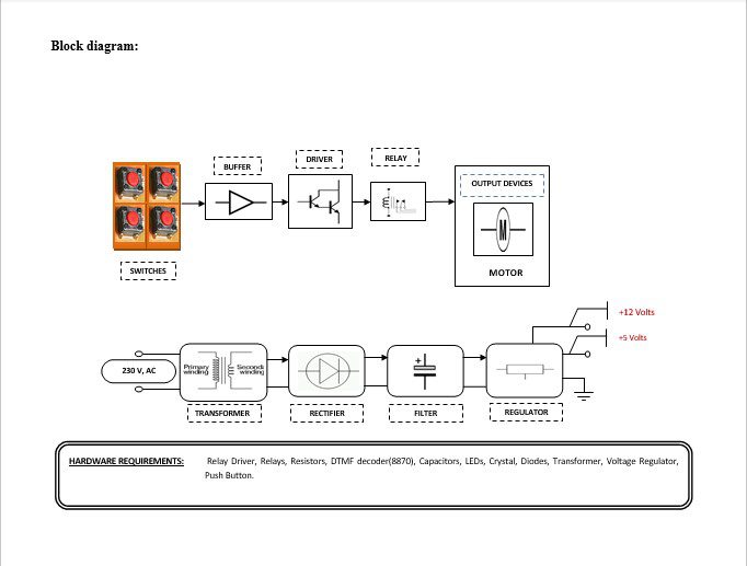
Block diagram explanation :
Power supply unit:
This section needs two voltages viz., +12 V & +5 V, as working voltages. Hence specially designed power supply is constructed to get regulated power supplies.
Buffers:
Buffers do not affect the logical state of a digital signal (i.e. a logic 1 input results in a logic 1 output whereas logic 0 input results in a logic 0 output). Buffers are normally used to provide extra current drive at the output but can also be used to regularize the logic present at an interface.
Drivers:
This section is used to drive the relay where the output is the complement of input which is applied to the drive but the current will be amplified.
Relays:
It is an electromagnetic device that is used to drive the load connected across the relay and the o/p of the relay can be connected to the controller or load for further processing.
Indicator:
This stage provides a visual indication of which relay is actuated and deactivated, by glowing respective LED or Buzzer.
Methodology:
The above block diagram shows the setup of the Electronic Jack to turn On / Off Of the Motor to lift the heavy load. When we press the switches the output is fed to the buffer IC 4050, the buffer stores and is given to the driver IC 2003 in the driver current will amplify and voltage will invert with the help of the Darlington circuit of driver IC to drive the relay. Then the signal is given to the motor to turn ON or OFF.
Advantages:
- No need for human effort.
- Jack can control both remotely as well as manually.
- Heavy things can lift easily.
Disadvantages:
Power is needed.
Applications:
- Can be used by physically handicapped persons to lift cars or other things.
- Can be used in workshops or for personal use.


