Table of Contents
Introduction:


An IVR system is used to collect and provide information to a caller through an automated process. This allows the caller to be helped with minimal or no interaction with an actual human.
In an IVR system, a call is answered automatically when it is received, and a prerecorded message is played over the call. This message usually offers callers choices, such as “Press one to talk to customer service, press two to talk to accounting….” Callers can then press a touch-tone button on their phones, generating a tone that the IVR system can detect. The call is then routed according to the response from the caller.
An IVR system can also collect additional numeric information from the caller. For example, a student may call the college service line. The caller enters their Student ID through the phone pad. The IVR system can collect that information, look up information related to ID and provide that information to the caller.
A telephone is one of the most common and useful consumer electronics gadgets in the world today. It incorporates both Communication & Digital Electronics filed. They provide us with countless conveniences in our daily lives.
As the device is so much popular and part of every-day-activities, many add-on circuits are constructed to make it a still more feature-rich instrument. And one such add-on feature is this system which allows the user to switch ON/OFF loads from the remote end. It finds applications in homes, offices, and even in industries.
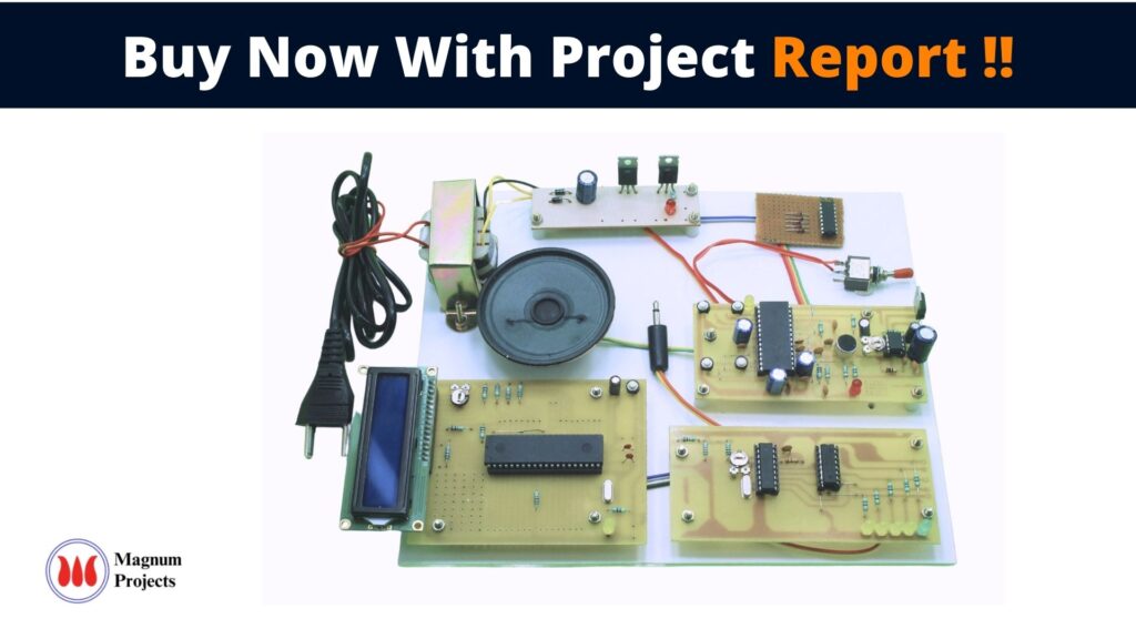
Here is a telephone-operated device control circuit that enables switching the ‘on’ and ‘off’ of appliances through telephone lines. It can be used to switch appliances from any distance, overcoming the limited range of infrared and radio remote control.


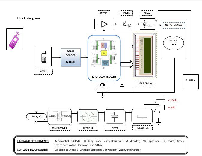
Block diagram explanation :
Power supply unit:
This section needs two voltages viz., +12 V & +5 V, as working voltages. Hence specially designed power supply is constructed to get regulated power supplies.
Buffers:
Buffers do not affect the logical state of a digital signal (i.e. a logic 1 input results in a logic 1 output whereas logic 0 input results in a logic 0 output). Buffers are normally used to provide extra current drive at the output but can also be used to regularize the logic present at an interface.
Microcontroller:
The 89C51 Microcontroller is the heart of this project. It is the chip that processes the User Data and executes the same. The software inherited in this chip manipulates the data and sends the result for visual display.
The general definition of a microcontroller is a single-chip computer, which refers to the fact that they contain all of the functional sections (cpu, ram, rom, i/o, ports, and timers) of a traditionally defined computer on a single integrated circuit. Some experts even describe them as special-purpose computers with several qualifying distinctions that separate them from other computers.
Features Of Microcontroller :
- 8K Bytes of In-System Reprogrammable Flash Memory
- Endurance: 1,000 Write/Erase Cycles
- Fully Static Operation: 0 Hz to 24 MHz
- Three-level Program Memory Lock
- 256 x 8-bit Internal RAM
- 32 Programmable I/O Lines
- Three 16-bit Timer/Counters
Drivers:
This section is used to drive the relay where the output is the complement of input which is applied to the drive but the current will be amplified.
Relays:
It is an electromagnetic device that is used to drive the load connected across the relay and the o/p of the relay can be connected to the controller or load for further processing.
Indicator:
This stage provides a visual indication of which relay is actuated and deactivated, by glowing respective LED or Buzzer.
DTMF Decoder:
The DTMF decoder used is CM8870. It is used to decode the mobile’s audio signal, i.e., the keypad tone. When the user presses a button on the keypad of the mobile, it generates two tones at the same time. These tones are taken from a table comprising a row frequency and a column frequency. Thus the resulting frequency signal is known as the “Dual Tone Multi-Frequency” signal. A DTMF signal is an algebraic sum of two different frequencies, one from the row frequency (higher frequency) group and another from the low frequency (column frequency) group. The CM8870 decodes the received DTMF tone and then sends its equivalent binary code to the microcontroller. According to the program loaded into the microcontroller, the corresponding action starts.
Methodology:
This system is connected to the telephone lines in parallel to the user’s Telephone Set. Whenever the call comes, detects it and starts counting the number of rings. If the rings are equal to a pre-defined number, say five, it simply means the user is not present and the system has to attend to the call. So the system switches the call to this unit so that it can detect the commands sent by the caller. Depending upon the key pressed by the caller, the respective load goes ON/OFF or latches.
Advantages:
- It senses the “real” telephone ring.
- Automatically switches the call to this system, after predefined rings.
- Switches ON/OFF The load depends upon the key pressed by the caller.
Disadvantages:
If GSM fails to catch the network then failure of controlling the devices.
Applications:
- IVRS Telephonic Alerts: Calls are made to customers, prospective customers, employees, or other stakeholders to provide them with some useful information (stock quotes, new schemes, etc) or other critical information.
- IVRS Surveys: IVRS can be very effectively used to conduct customer satisfaction as well as employee satisfaction surveys.
- IVRS Reservations: IVRS can be well used in cinema halls, restaurants, airlines, etc for reservation purposes. In the age of speech-enabled IVRS, it has given a more convenient way to book tickets or spaces.
4.IVRS Status Information: IVRS/IVR application can be used for letting the customer know about his application status, ticket status, air flight status, project.


