Table of Contents
Introduction:


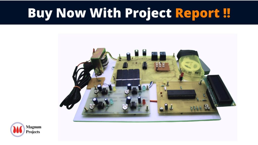
The main consideration in the present field of technologies is Automation, Power consumption, and cost-effectiveness. Automation is intended to reduce manpower with the help of intelligent systems. Power saving is the main consideration forever as the source of the power(Thermal, Hydro, etc.,) is getting diminished due to various reasons. The main aim of the project is an Automatic street power-saving system with LDR; this is to save power. We want to save power automatically instead of doing it manually. So it’s easy to make it cost-effective. This saved power can be used in some other cases. So in villages, towns, etc, we can design intelligent systems for the usage of street lights


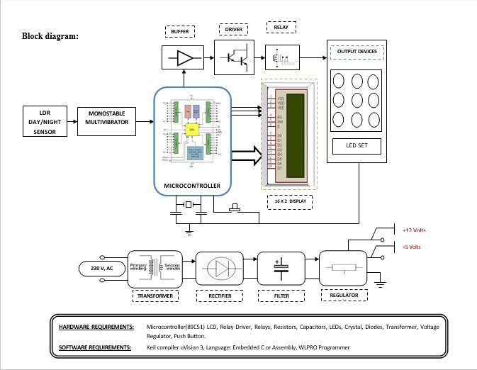
Block diagram explanation :
Power supply unit:
This section needs two voltages viz., +12 V & +5 V, as working voltages. Hence specially designed power supply is constructed to get regulated power supplies.
Microcontroller:
The 89C51 Microcontroller is the heart of this project. It is the chip that processes the User Data and executes the same. The software inherited in this chip manipulates the data and sends the result for visual display.
The general definition of a microcontroller is a single-chip computer, which refers to the fact that they contain all of the functional sections (cpu, ram, rom, i/o, ports, and timers) of a traditionally defined computer on a single integrated circuit. Some experts even describe them as special-purpose computers with several qualifying distinctions that separate them from other computers.
Features Of Microcontroller :
- 8K Bytes of In-System Reprogrammable Flash Memory
- Endurance: 1,000 Write/Erase Cycles
- Fully Static Operation: 0 Hz to 24 MHz
- Three-level Program Memory Lock
- 256 x 8-bit Internal RAM
- 32 Programmable I/O Lines
- Three 16-bit Timer/Counters
Buffers:
Buffers do not affect the logical state of a digital signal (i.e. a logic 1 input results in a logic 1 output whereas logic 0 input results in a logic 0 output). Buffers are normally used to provide extra current drive at the output but can also be used to regularize the logic present at an interface.
Drivers:
This section is used to drive the relay where the output is the complement of input which is applied to the drive but the current will be amplified.
Relays:
It is an electromagnetic device that is used to drive the load connected across the relay and the o/p of the relay can be connected to the controller or load for further processing.
Indicator:
This stage provides a visual indication of which relay is actuated and deactivated, by glowing respective LED or Buzzer.
Methodology:
The daylight sensor is used to activate the LED sets depending on the impact of the natural light. When the nighttime light level is low the resistance of the LDR is high. This prevents current from flowing to the base of the transistors. Consequently, the LED set will be turned ON. However, when in the daytime light shines onto the LDR its resistance falls, and current flows into the base of the first transistor and then the second transistor. The LED set will be turned OFF.
Advantages:
- In general mode, the power savings is about 50%.
- In dim mode, it is about 35%.
- The utilization of energy is optimized using this technology.
- Street light gives a bright light over a semi-circle of a radius of 30 feet.
Disadvantages:
- Operative and maintenance are cost-effective.
- Initial and maintenance cost is high.
Applications:
- This system is designed for outdoor applications in un-electrified rural areas.
- This system is an ideal application for campus and village street lighting
- The solar street light system is an ideal lighting system for roads, yards, residential colonies, township, corporate offices, hospitals educational institutions, and rural electrification.


