Table of Contents
Introduction:

The project presented here is a novel approach to vehicle navigation & safety implementation. As the title suggests, the project is aimed at automatically sensing the areas/zones like “School Zone”, “Hospital Zone” or “Accident Zone”.
In convention, these special zones or areas are indicated at the roadside on a pillar or road sign pole.
As an example, near a school zone, the sign board displays “School Zone Ahead, Drive Slowly”, or near a hospital, “Hospital Area-Do not Blow Horn”, but in reality rarely this is practice. Drivers go at very high speeds as usual near the school zone or operate the harsh horns loudly causing inconvenience to the patients in the hospital. Even though these are meant for the safety of the vehicles traveling and also for the general public, it is hardly practiced by vehicle drivers. As a result, making the whole concept of displaying warning signs and messages on the roadside boards is meaningless.
To provide a better alternative, one can develop a system that will automatically sense such traffic signs automatically and accordingly inform the drivers and also assist them in controlling the vehicle voluntarily or forcibly. All in all, resulting in a very effective and fail-proof system to provide traffic regulation, safety, and convenience to the people.
As the whole project is not just limited to these few functions, this project can be made mandatory. That way one can provide a more reliable security device and streamline traffic flow. A few additional features which can be integrated with this system are, “Down Hill Detection”, “Auto-Breaking with Obstacle Detection” “auto Speed limit Sensor” etc.

Block diagram explanation :
Power supply unit:
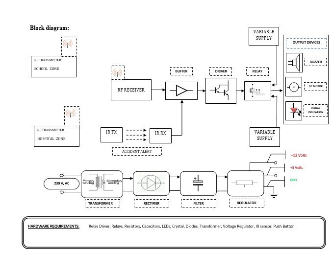
This section needs two voltages viz., +12 V & +5 V, as working voltages. Hence specially designed power supply is constructed to get regulated power supplies.
Buffers:
Buffers do not affect the logical state of a digital signal (i.e. a logic 1 input results in a logic 1 output whereas logic 0 input results in a logic 0 output). Buffers are normally used to provide extra current drive at the output but can also be used to regularize the logic present at an interface.
Drivers:
This section is used to drive the relay where the output is the complement of input which is applied to the drive but the current will be amplified.
Relays:
It is an electromagnetic device that is used to drive the load connected across the relay and the o/p of the relay can be connected to the controller or load for further processing.
Indicator:
This stage provides a visual indication of which relay is actuated and deactivated, by glowing respective LED or Buzzer.
IR Transmitter and Receiver:
Infrared (IR) transmitters and receivers are present in many different devices, though they are most commonly found in consumer electronics. The way this technology works is that one component flashes an infrared light in a particular pattern, which another component can pick up and translate into an instruction. These transmitters and receivers are found in remote controls and all different types of devices, such as televisions and DVD players. Peripheral devices that include this technology can also allow a computer to control various other consumer electronics. Since infrared remotes are limited to line-of-sight operation, some products can be used to extend the signals over a hardwired line or radio frequency (RF) transmissions.
RF transmitter:
This is a 2-channel Radio Frequency Transmitter specially tuned with its RF Receiver part in carrier frequency. Each zone is set with one channel and transmits its presence to the moving vehicle’s RF Receiver unit.
RF receiver:
This is also a 2-channel RF Receiver specially tuned with its counterpart RF Transmitter in carrier frequency. When the vehicle enters any zone that zones RF signals are received by this unit. Thus depending upon the channel signals it receives from the transmitting end the channel output of the RF Receiver goes HIGH. This HIGH signal is fed to the controller chip through Buffer & Driver and Switching stage for further processing.
Methodology:
This ‘Smart Zone Sensing System with Automatic Control’ system works like this. Each monitoring zones are fitted with RF Transmitter units with a unique Identity Code. All the vehicles must be fitted with RF receivers and respective circuitry on their vehicle’s number plate. The display will be fitted on the dashboard for a visual representation of the alert messages sent by respective zone Transmitters.
The Radio Frequency Transmitter transmits the zoning code to the receiving units. There are two zones in the present system: School Zone and Hospital Zone. Each Transmitter has carried its frequency. The Radio Frequency Receiver receives the Zone Code transmitted by the Transmitter. According to the frequency of the transmitter, here for Transmitter #1 & #2 respective output pins go high. The output is fed to Buffer. This unit provides unit gain amplification to the received Zone Code signal and drives the relay for further feeding. The output of the Zone Code signal is fed to the Microcontroller chip as input and gets Speed Limit & Low Horn commands from it and drives the two more blocks.
If an obstacle still comes near to vehicle then it must stop the vehicle automatically. It is possible to construct such a system using one IR Transmitter and two IR Receivers with slightly less efficiency than one another. The working of the system is explained in the Brief of Block Diagram & its Description section.
The system’s IR Transmitter and IR Receivers must be fitted in front of the vehicle and the system must be supplied with power only when the vehicle starts moving. That means the power supply line of the system must be in series with the ignition key of the vehicle, and when the rider switches ON the ignition key vehicle starts and the system comes into action.
Advantages:
- This application is very useful for any kind of vehicle.
- This application is easy to install and easy to operate.
- Manpower can be saved by implementing auto-detecting circuits.
- More reliable than manual Operation.
Disadvantages:
- One-time investment cost.
Applications:
- The project is used to secure and avoid road accidents.
- It can be used as part of the automation of s or Public Transportation.
- This system is used to trace the culprit vehicles by police persons.
- This project can also be used by Cargo Companies to intimate their on-road vehicles about the next delivery spot or assignment.
- This system can be used for ‘timekeeping’ purposes in public transportation, such as departure & arrival timings, the number of rotations each vehicle turned, etc.


