Table of Contents
Introduction:


Conventionally Wireless-controlled Robots use RF circuits, which have limited working range, limited frequency range, and limited control. The use of a mobile phone for robotic control can overcome these limitations. It provides the advantage of robust control, a working range as large as the area of the service provider, and no interference with other controllers. Although the appearance and capabilities of robots vary vastly, all robots share the feature of a mechanical, movable structure under some form of control. The control of the Robot involves three distinct phases: perception, processing, and action. Generally, the preceptors are sensors mounted on the robot, the processing is done by the onboard microcontroller or processor, and the task is performed using motors or some other actuators. In this project, the robot is connected to a GSM modem which is controlled by the user’s mobile phone. With the help of AT commands, we can move our robot in the desired direction as per our requirements.


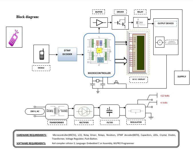
Block diagram explanation :
Power supply unit:
This section needs two voltages viz., +12 V & +5 V, as working voltages. Hence specially designed power supply is constructed to get regulated power supplies.
Buffers:
Buffers do not affect the logical state of a digital signal (i.e. a logic 1 input results in a logic 1 output whereas logic 0 input results in a logic 0 output). Buffers are normally used to provide extra current drive at the output but can also be used to regularize the logic present at an interface.
Microcontroller:
The 89C51 Microcontroller is the heart of this project. It is the chip that processes the User Data and executes the same. The software inherited in this chip manipulates the data and sends the result for visual display.
The general definition of a microcontroller is a single-chip computer, which refers to the fact that they contain all of the functional sections (cpu, ram, rom, i/o, ports, and timers) of a traditionally defined computer on a single integrated circuit. Some experts even describe them as special-purpose computers with several qualifying distinctions that separate them from other computers.
Features Of Microcontroller :
- 8K Bytes of In-System Reprogrammable Flash Memory
- Endurance: 1,000 Write/Erase Cycles
- Fully Static Operation: 0 Hz to 24 MHz
- Three-level Program Memory Lock
- 256 x 8-bit Internal RAM
- 32 Programmable I/O Lines
- Three 16-bit Timer/Counters
Drivers:
This section is used to drive the relay where the output is the complement of input which is applied to the drive but the current will be amplified.
Relays:
It is an electromagnetic device that is used to drive the load connected across the relay and the o/p of the relay can be connected to the controller or load for further processing.
Indicator:
This stage provides a visual indication of which relay is actuated and deactivated, by glowing respective LED or Buzzer.
DTMF Decoder:
The DTMF decoder used is CM8870. It is used to decode the mobile’s audio signal, i.e., the keypad tone. When the user presses a button on the keypad of the mobile, it generates two tones at the same time. These tones are taken from a table comprising a row frequency and a column frequency. Thus the resulting frequency signal is known as the “Dual Tone Multi-Frequency” signal. A DTMF signal is an algebraic sum of two different frequencies, one from the row frequency (higher frequency) group and another from the low frequency (column frequency) group. The CM8870 decodes the received DTMF tone and then sends its equivalent binary code to the microcontroller. According to the program loaded into the microcontroller, the corresponding action starts.
Methodology:
The project presented here is an advanced Robotic System that can be controlled via a GSM Network & GSM Mobile equipment. As shown in the Block Diagram, the project consists of a set of GSM equipment via; GSM Mobile Handset & GSM Mobile Infrastructure. Through a mobile handset one can dial the assigned number for that particular Robotic Vehicle & after the reception of the acknowledgment signal, one can send the Control Signals in the form of DTMF codes via handset. Here each DTMF tone resembles a specific activity of the Robotic Vehicle and accordingly, the Robotic Vehicle generates the actions. These actions can be either movement of the Robotic Vehicle.
Advantages:
- This is a novel approach to Robotic Automation.
- This project is not limited by any geographical limit for operation except the availability of a GSM network
- Economical in nature compared to conventional systems & highly reliable.
Disadvantages:
If GSM fails to catch the network then failure of controlling the devices.
Applications:
- Automation.
- Safety Monitoring.
- Assistance to Disabled Persons.
- Standalone Security System.


