Table of Contents
Introduction:


The project presented here is an advanced system in the field of Automation of the Railway Department. This project is going to facilitate us with various essential & critical features associated with Railways Safety & Monitoring.
The highlight of this Embedded Safety Tool is that this single system is going to help us in Monitoring & Controlling the Railway Safety parameters like;
- Station Name display in Train.
- Automatic station alerted/vibrator.
- Fire & smoke detector in train.


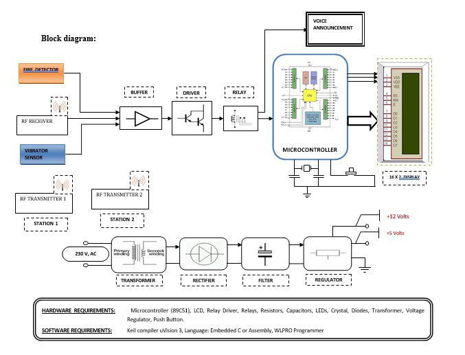
Block diagram explanation :
Power supply unit:
This section needs two voltages viz., +12 V & +5 V, as working voltages. Hence specially designed power supply is constructed to get regulated power supplies.
Buffers:
Buffers do not affect the logical state of a digital signal (i.e. a logic 1 input results in a logic 1 output whereas logic 0 input results in a logic 0 output). Buffers are normally used to provide extra current drive at the output but can also be used to regularize the logic present at an interface.
Drivers:
This section is used to drive the relay where the output is the complement of the input which is applied to the drive but the current will be amplified.
Relays:
It is an electromagnetic device that is used to drive the load connected across the relay and the o/p of the relay can be connected to the controller or load for further processing.
Indicator:
This stage provides a visual indication of which relay is actuated and deactivated, by a glowing respective LCD or Buzzer.
RF transmitter:
This is a 2-channel Radio Frequency Transmitter specially tuned with its RF Receiver part in carrier frequency. Each zone is set with one channel and transmits its presence to the moving vehicle’s RF Receiver unit.
RF receiver:
This is also a 2-channel RF Receiver specially tuned with its counterpart RF Transmitter in carrier frequency. When the vehicle enters any zone that zones RF signals are received by this unit. Thus depending upon the channel signals it receives from the transmitting end the channel output of the RF Receiver goes HIGH. This HIGH signal is fed to the controller chip through Buffer & Driver and Switching stage for further processing.
Voice recorder:
The APR9600 device offers true single-chip voice recording, non-volatile storage, and playback capability for 40 to 60 seconds. The device supports both random and sequential access to multiple messages.
Sample rates are user-selectable, allowing designers to customize their designs for unique quality and storage time needs. Integrated output amplifiers, microphone amplifiers, and AGC circuits greatly simplify system design. many other consumer and industrial applications.
APLUS integrated achieve these high levels of storage capability by using its proprietary analog/multilevel storage technology implemented in an advanced Flash non-volatile memory process, where each memory cell can store 256 voltage levels. This technology enables the APR9600 device to reproduce voice signals in their natural form. It eliminates the need for encoding and compression, which often introduce distortion.
Microcontroller:
The 89C51 Microcontroller is the heart of this project. It is the chip that processes the User Data and executes the same. The software inherited in this chip manipulates the data and sends the result for visual display.
The general definition of a microcontroller is a single-chip computer, which refers to the fact that they contain all of the functional sections (cpu, ram, rom, i/o, ports, and timers) of a traditionally defined computer on a single integrated circuit. Some experts even describe them as special-purpose computers with several qualifying distinctions that separate them from other computers.
Features Of Microcontroller :
- 8K Bytes of In-System Reprogrammable Flash Memory.
- Endurance: 1,000 Write/Erase Cycles.
- Fully Static Operation: 0 Hz to 24 MHz
- Three-level Program Memory Lock.
- 256 x 8-bit Internal RAM.
- 32 Programmable I/O Lines.
- Three 16-bit Timers/Counters.
Methodology:
The above block diagram shows the setup of Railway Automation using temperature, Vibrator, RF & Microcontroller.
- Station Name Display in train:
As the station approaches, the station name will be displayed on the screen inside the train. There is a RF transmitter fitted in the station and the receiver is fitted in the train. The transmitter sends the code of the station and it is read by the train receiver.
2. Automatic Station alerted/vibrator:
As the station approaches, the respective station dropping passenger’s seat vibrator/more alert starts activating inside the train. There is a transmitter fitted in the station and the receiver is fitted in the train. The transmitter sends the code of the station and it is read by the train receiver.
3. Fire and smoke detector in train:
There are temperature sensors in every bogie, so if there is any fire or smoke then the beeper beeps and we will get a verbal message.
Advantages:
- Fully automatic
- Low power consumption
- Low cost to design the circuit, maintenance of the circuit is good
- Easy convenience to handle.
Disadvantages:
- One-time investment cost.
- It has to be planted throughout the city.
Applications:
- Industries.
- Buses.


