Table of Contents
Introduction:


LiFi is the transmission of data through illumination by taking the fiber out of fiber optics by sending data through a LED light bulb that varies in intensity faster than the human eye can follow. Li-Fi is the term some have used to label the fast and cheap wireless communication system, which is the optical version of Wi-Fi. The term was first used in this context by Harald Haas in his TED Global talk on Visible Light Communication. “At the heart of this technology is a new generation of high brightness light-emitting diodes”, says Harald Haas from the University of Edinburgh, UK,” Very simply, if the LED is on, you transmit a digital 1, if it’s off you transmit a 0,” Haas says, “They can be switched on and off very quickly, which gives nice opportunities for transmitted data.”It is possible to encode data in the light by varying the rate at which the LEDs flicker on and off to give different strings of 1s and 0s. The LED intensity is modulated so rapidly that the human eye cannot notice, so the output appears constant. More sophisticated techniques could dramatically increase the VLC data rate. Terms at the University of Oxford and the University of Edinburgh are focusing on parallel data transmission using an array of LEDs, where each LED transmits a different data stream. Other groups are using mixtures of red, green, and blue LEDs to alter the light frequency encoding a different data channel. Li-Fi, as it has been dubbed, has already achieved blisteringly high speed in the lab. Researchers at the Heinrich Hertz Institute in Berlin, Germany, have reached data rates of over 500 megabytes per second using a standard white-light LED. The technology was demonstrated at the 2012 Consumer Electronics Show in Las Vegas using a pair of Casio smartphones to exchange data using light of varying intensity given off from their screens, detectable at a distance of up to ten meters.


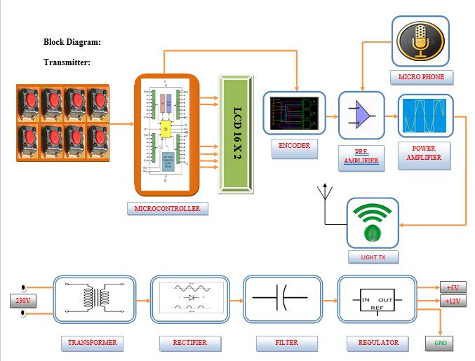
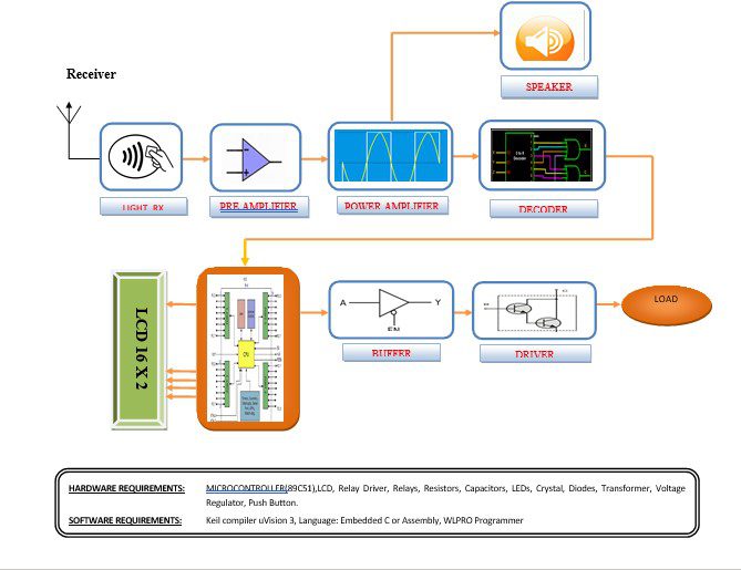
Block diagram explanation:
Power supply unit
This section needs two voltages viz., +12 V & +5 V, as working voltages. Hence specially designed power supply is constructed to get regulated power supplies.
Microcontroller:
The Atmel AT89 series is an Intel 8051-compatible family of 8-bit microcontrollers (µCs) manufactured by the Atmel Corporation. Based on the Intel 8051 core, the AT89 series remains very popular as general-purpose microcontrollers, due to their industry standard instruction set, and low unit cost. This allows a great amount of legacy code to be reused without modification in new applications. While considerably less powerful than the newer AT90 series of AVR RISC microcontrollers, new product development has continued with the AT89 series for the aforementioned advantages
Preamplifier:
A preamplifier (preamp) is an electronic amplifier that prepares a small electrical signal for further amplification or processing. A preamplifier is often placed close to the sensor to reduce the effects of noise and interference. It is used to boost the signal strength to drive the cable to the main instrument without significantly degrading the signal-to-noise ratio(SNR)
Power amplifier:
An audio power amplifier is an electronic amplifier that amplifies low-power audio signals (signals composed primarily of frequencies between 20 – 20 000 Hz, the human range of hearing) to a level suitable for driving loudspeakers. It is the final electronic stage in a typical audio playback chain.
Li-Fi transmitter and receiver:
Li-Fi is implemented using white LED light bulbs at the downlink transmitter. These devices are used for illumination only by applying a constant current. By fast and subtle variations of the current, optical output can be made to vary at extremely high speeds. This variation is used to carry high-speed data.
Buffers
Buffers do not affect the logical state of a digital signal (i.e. a logic 1 input results in a logic 1 output whereas logic 0 input results in a logic 0 output). Buffers are normally used to provide extra current drive at the output but can also be used to regularize the logic present at an interface
Drivers
This section is used to drive the relay where the output is the complement of input which is applied to the drive but the current will be amplified
Relays
It is an electromagnetic device that is used to drive the load connected across the relay and the o/p of the relay can be connected to the controller or load for further processing.
Methodology:
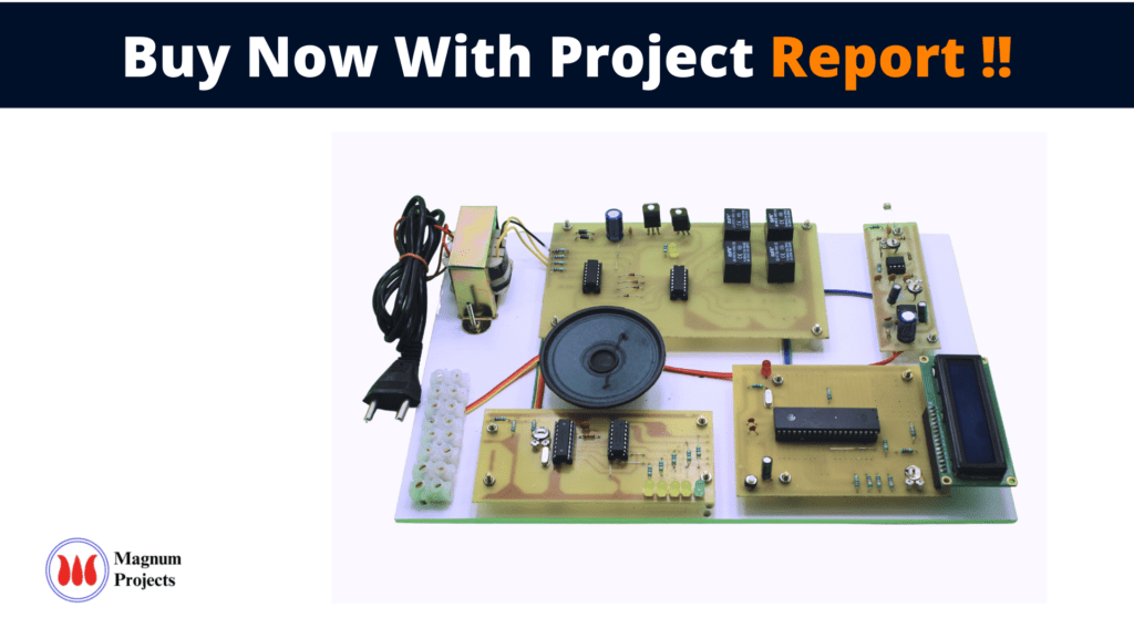
In the process of data communication through the visible light on the transmitter side, Keypad is used as the input signal. The microcontroller receives the signal from the keypad and generates two outputs and gives that signal to the DTMF Encoder. The encoder will generate one tone and one frequency for every pressed key. That frequency is amplified by the amplifier circuits and fed into the power LED. At the receiver side light dependant resister will receive the light signal and correspondingly generate an electrical signal proportional to it. This electrical signal is processed by a demodulator circuit(DTMF Decoder), and the output of the decoder is then fed to a microcontroller and the microcontroller activates the corresponding load for the pressed key.
In the process of voice communication through the visible light on the transmitter side voice is used as the input signal. This signal is converted to an electrical signal through a condenser or microphone. This electrical signal is amplified by the amplifier circuits and fed into the power LED. The light signal from the LED varies according to the intensity of the voice signal. The louder the voice the more glow the LED will be. At the receiver side light dependant resister will receive the light signal and correspondingly generate an electrical signal proportional to it. This electrical signal is processed by a demodulator circuit, which is then fed to a speaker and produces the audio signal which was at the input of the transmitter side.
Advantages
1. Harmless for the human body.
2. Data transmission by sockets of existing light fixtures.
3. Alleviation of problems associated with the radio frequency (RF) communication system.
4. Less energy consumption.
5. Increased security.
6. Compact integration of sensors through small dimensions.
7. Huge number of channels available without interfering with other sources.
8. Simple electronics such as the drive for the LEDs.
9. No influence on other sensitive equipment through radio waves.
Disadvantages:
1. To transmit the data it should be in the line of sight.
Applications:
- Aviation
- Smart Lighting
- Hazardous Environments
- Device Connectivity
- Vehicle and Transportation
- Defense and Security
- Hospitals
- Underwater Communications


