Table of Contents
Intoduction:


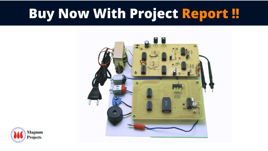
The Automatic Green House Model project is an advanced and innovative system for the automatic monitoring & controlling of the Green House Systems. In the conventional method, the parameters like Soil Moisture i.e., Water; Water Intensity & Temperature are manually controlled to produce food grains/vegetables or fruits. This process is time-consuming & requires manpower to study & control these physical parameters.
Here, the Automatic Green House Model project is designed to measure & control the above-said parameters automatically and efficiently without manual attention & intervention. This project helps us to eliminate the manpower requirement and also to use resources like water & electricity very efficiently.
Monitoring is the first step to understanding and fixing almost all issues. Manual irrigation is labor-intensive and repetitive, so it is one of the first greenhouse tasks that should be automated. Although automating irrigation is easy, automated systems are not necessarily water efficient. Many growers use timers to control irrigation, but timers do not account for day-to-day changes in plant water use caused by natural fluctuations in temperature, light, and humidity levels. In addition, plant water use increases as plants grow. This makes it difficult to obtain efficient irrigation using a timer. Given the increasing strain on water resources in many parts of North America, the greenhouse industry needs to move towards more efficient irrigation systems. Humiditygives the percentage of water in the air.
Water saving is the main aim of our work. A very small amount of water is useful for all living organisms and it’s the human being who is mainly responsible for the wastage of water. There are many sources by which human makes water hazardous for other living organisms plus there are many ways by which human being is responsible for the wastage of water. One major reason for this is the unnecessary wastage of water in agricultural fields due to the unawareness of farmers about the sufficient supply of water. Many plants are very sensitive to water levels and they required a specific level of water supply for proper growth, if this is not they may die or result in improper growth.


Block diagram explanation:
Power supply unit:
This section needs two voltages viz., +12 V & +5 V, as working voltages. Hence specially designed power supply is constructed to get regulated power supplies.
Temperature sensor:
Thermistors are thermally sensitive resistors whose prime function is to exhibit a large, predictable, and precise change in electrical resistance when subjected to a corresponding change in body temperature. Negative Temperature Coefficient (NTC) Thermistors exhibit a decrease in electrical resistance when subjected to an increase in body temperature and Positive Temperature Coefficient (PTC) thermistors exhibit an increase in electrical resistance when subjected to an increase in body temperature.
Buffers:
Buffers do not affect the logical state of a digital signal (i.e. a logic 1 input results in a logic 1 output whereas logic 0 input results in a logic 0 output). Buffers are normally used to provide extra current drive at the output but can also be used to regularize the logic present at an interface.
Drivers:
This section is used to drive the relay where the output is a complement of input that is applied to the drive but the current will be amplified.
Relays:
It is an electromagnetic device that is used to drive the load connected across the relay and the o/p of the relay can be connected to the controller or load for further processing.
Indicator:
This stage provides a visual indication of which relay is actuated and deactivated, by glowing respective LED or Buzzer.
Methodology:
This project is developed to reduce the workload of a Former and to sense the parameters like Temperature and conductivity. After sensing that parameter depending on the scenario the motor will get activated via Buffer and driver stage. The module has two motors, one motor for a temperature sensor and another motor for a conductivity sensor as well as for manual activation of the motor via mobile. If the temperature is high then it activates the motor for sprinkling water. If the conductivity is low then the motor will be activated via buffer and driver. If a person wants to activate the motor at any time he can activate the motor via his cell phone.
Advantages:
- All the components required are easily available.
- It is accurate [Errors are nullified] & precise as it is Digital.
- Low power consumption.
- Less hardware involved and Cost Efficient.
- Automatically controlled & Easy to use.
- Unnecessary wastage of electricity can be controlled to a greater extent.
- Eliminate or at least minimize runoff
- Raise healthy plants
Disadvantages:
- In this project usage of relays leads to consuming more power.
- One-time investment.
Applications:
- This project can be implemented in homes, Schools, Colleges, Companies, etc…
- Where we have to reduce the workload of humans, former and to sense the parameters like temperature and conductivity there we can implement this project.


