Table of Contents
Introduction:


The satisfactory performance of an aircraft is dependent upon the continued reliability of the electrical system. Damaged wiring or equipment in an aircraft, regardless of how minor it may appear to be, cannot be tolerated. The reliability of the system is proportional to the amount of maintenance received and the knowledge of those who perform such maintenance. It is, therefore, important that maintenance be accomplished using the best techniques and practices to minimize the possibility of failure. This chapter is not intended to supersede or replace any government specification or specific manufacturer’s instruction regarding electrical system inspection and repair.


Block diagram explanation :
Power supply unit:
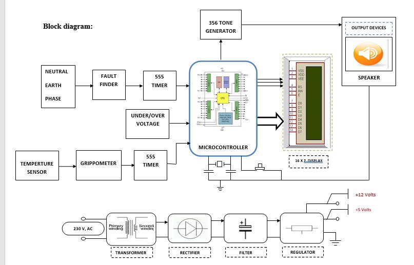
This section needs two voltages viz., +12 V & +5 V, as working voltages. Hence specially designed power supply is constructed to get regulated power supplies.
Buffers:
Buffers do not affect the logical state of a digital signal (i.e. a logic 1 input results in a logic 1 output whereas logic 0 input results in a logic 0 output). Buffers are normally used to provide extra current drive at the output but can also be used to regularize the logic present at an interface.
Microcontroller:
The 89C51 Microcontroller is the heart of this project. It is the chip that processes the User Data and executes the same. The software inherited in this chip manipulates the data and sends the result for visual display.
The general definition of a microcontroller is a single-chip computer, which refers to the fact that they contain all of the functional sections (CPU, ram, rom, i/o, ports and timers) of a traditionally defined computer on a single integrated circuit. Some experts even describe them as special-purpose computers with several qualifying distinctions that separate them from other computers.
Features Of Microcontroller :
- 8K Bytes of In-System Reprogrammable Flash Memory
- Endurance: 1,000 Write/Erase Cycles
- Fully Static Operation: 0 Hz to 24 MHz
- Three-level Program Memory Lock
- 256 x 8-bit Internal RAM
- 32 Programmable I/O Lines
- Three 16-bit Timer/Counters
Drivers:
This section is used to drive the relay where the output is the complement of the input which is applied to the drive but the current will be amplified.
Relays:
It is an electromagnetic device which is used to drive the load connected across the relay and the o/p of the relay can be connected to the controller or load for further processing.
Indicator:
This stage provides a visual indication of which relay is actuated and deactivated, by glowing respective LED or Buzzer.
Sensor:
A sensor is a converter that measures a physical quantity and converts it into a signal which can be read by an observer or by an (today mostly electronic) instrument. For example, a mercury-in-glass thermometer converts the measured temperature into expansion and contraction of a liquid which can be read on a calibrated glass tube. A thermocouple converts temperature to an output voltage which can be read by a voltmeter. For accuracy, most sensors are calibrated against known standards.
Methodology:
In the above block diagram shows the setup of the Ground Power Unit For aircraft. The job of this fault finder circuit which finds any fault in the Neutral, Earth, Phase in the transmission line. If any fault is detected then the output is fed to the microcontroller, which generates the output to turn ON the tone generator for indication. Like this over or under voltage and any fire is detected in the aircraft then turn ON the tone generator for indication.
Advantages:
- Effective in implementation.
- Low power consumption, and compact size,
- High reliability, due to the usage of power semiconductor devices,
- Greater control range due to the usage of Frequency Modulation with a PC.
Applications:
- Automotive.
- Instrumentation.
- Medical electronic
- Alarm systems.
- Instrumentation.
- Medical electronic.
- Alarm systems.
- Industrial electronics.


